Composite air/hydrocarbon trap filter assembly

a technology of hydrocarbon trap filter and composite filter, which is applied in the direction of filtration separation, combustion-air/fuel-air treatment, and separation processes, etc., can solve the problems of affecting the performance of the composite filter, and reducing the surface area available. , to achieve the effect of increasing the surface area available, improving the performance of the composite filter, and increasing the performan

Active Publication Date: 2010-01-12
ADVANCED FLOW ENG
View PDF14 Cites 28 Cited by
  • Summary
  • Abstract
  • Description
  • Claims
  • Application Information

AI Technical Summary

Benefits of technology

[0008]1) A new carbon trap filter, for inhibiting the egress of environmentally unfriendly emissions into the atmosphere, has a generally cylindrical shape. The carbon trap filter is formed with one (and possible more) layers of granulated activated charcoal (GAC) sandwiched between layers of porous material such as plastic netting and / or non-woven unipolyurethene surrounds an open core. The filter extends from a sealed upstream end to an open downstream end. The porous filter media and GAC may be confined within a suitable wire mesh to provide structural strength and rigidity;
[0011]The two filters, referred to generically as generally cylindrical, may be straight, i.e., in the shape of a right cylindrical or tapered with a circular cross-section of an increasing diameter towards the downstream end i.e., forming a conical section (“frustoconical”). The filters may also be provided with an elliptical or oval cross-section. Preferably, the carbon trap filter is pleated to maximize the surface area available for incoming and outgoing flow.
[0012]The improvement in performance of the composite filter of the present invention, we believe, is impressive. The factory system, as shown in the IDS photograph, when measured in AFE's factory, with a differential pressure of 1½ inches of water (across the combined filter assembly) provided a flow rate of 96 cubic feet per minute (“CFM”). In contrast, our composite filter assembly, when tested under the identical condition, i.e., pressure differential of 1½″ of water, provided a flow rate of 150 CFM, a 50% increase in performance.

Problems solved by technology

Such filters provide little help in preventing evaporative emissions from the intake manifold from entering the atmosphere.
Such emissions are a particular problem when the engine is turned off and the intake manifold is hot.
In addition to a carbon trap filter an air filter of conventional construction is necessary to remove particulate material, such as dirt or debris, often present in the air available which if not removed can cause substantial damages to the engine components.
This prior art dual filter assembly is very flow restrictive and as a result engine performance is compromised.

Method used


Image

  • Composite air/hydrocarbon trap filter assembly
  • Composite air/hydrocarbon trap filter assembly
  • Composite air/hydrocarbon trap filter assembly

Examples


Embodiment Construction

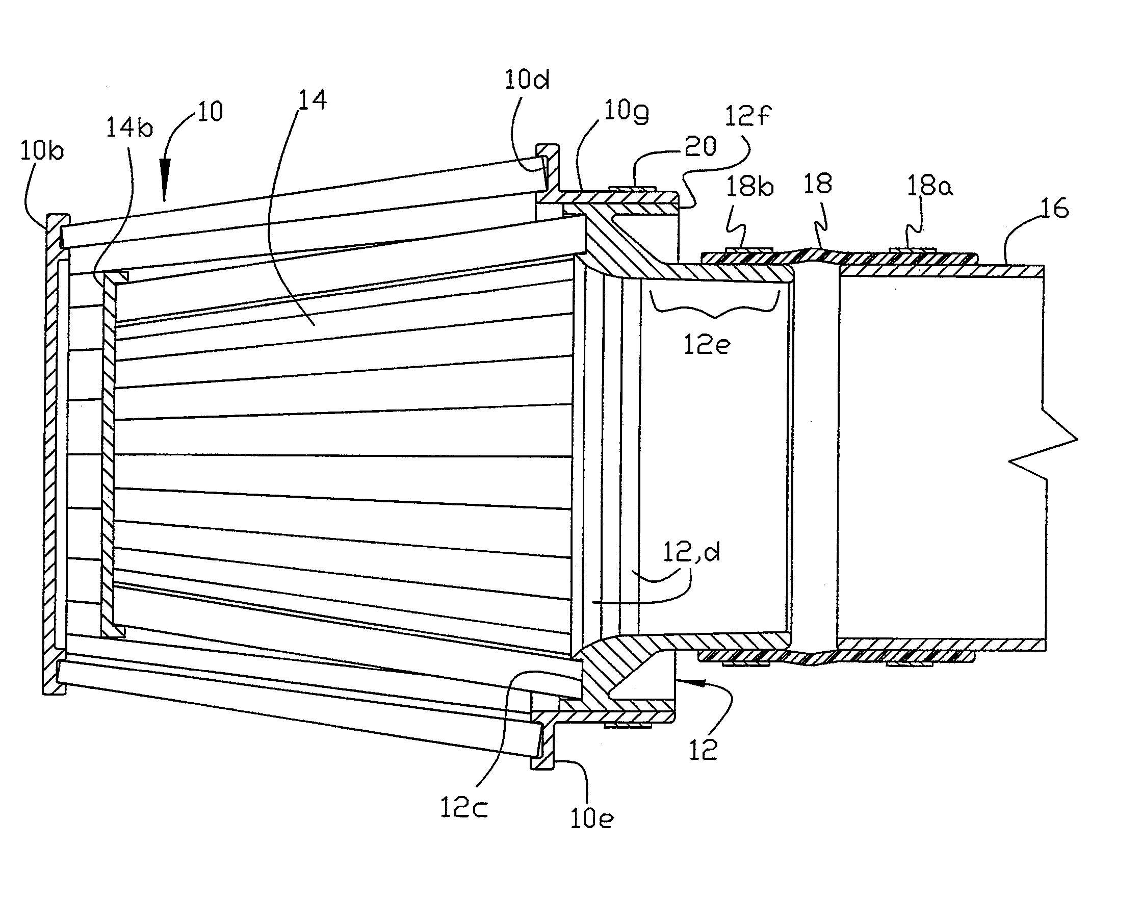
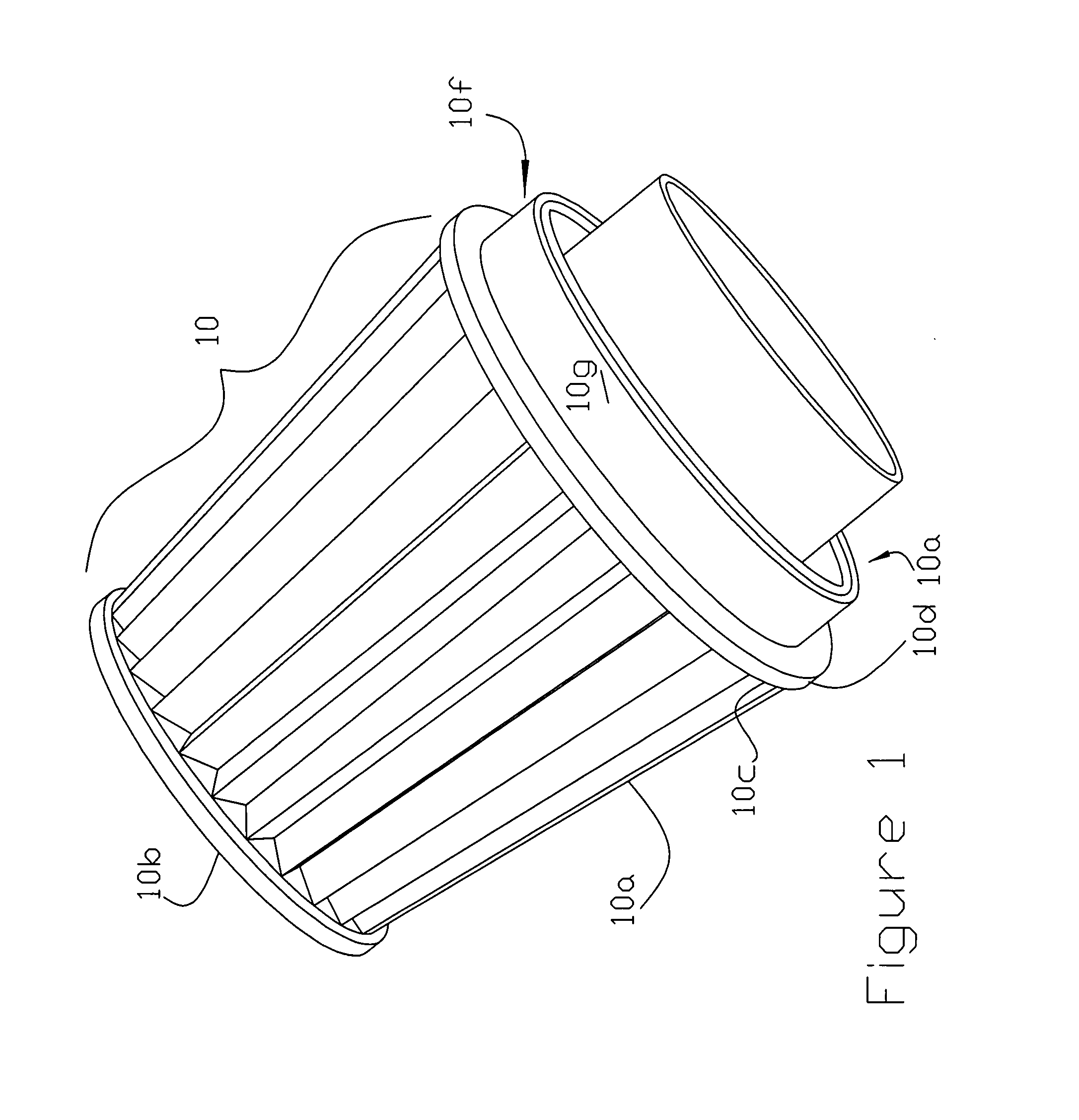
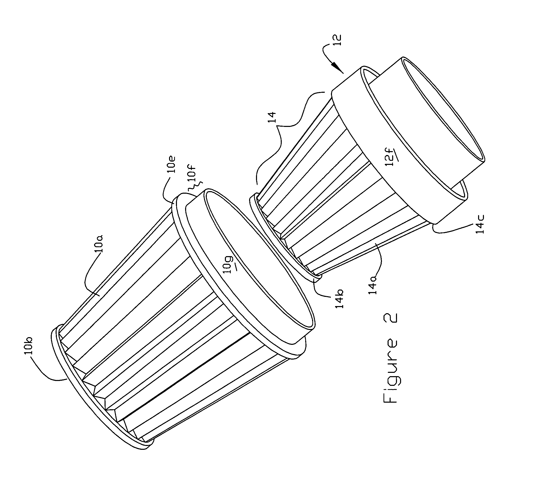
[0023]Referring now to the drawings and particularly to FIGS. 1-8 and 12 a conventional air filter 10 suitable for use in the present invention has a generally cylindrical shape (illustrated as frustoconical) with a pleated media side wall 10a extending between a sealed downstream end 10b (in the form of a conventional plastic disc) to upstream end 10c sealed (via a suitable bonding agent such as urethane) in a forwardly extending annular recess 10d (FIG. 12) formed in a rib 10e of an L-shaped support member 10f (FIG. 12). The support member 10f is formed with an axially projecting collar 10g arranged to be releasably secured to a flange 12f of the dual filter adapter 12 on which is mounted and sealed, e.g., via a urethane sealant, a carbon trap filter 14. See FIG. 2.

[0024]The carbon trap filter 14 also has a pleated side wall 14a extending from a sealed end 14b, also in the form of a plastic disc, to an upstream end 14c, sealed within a forwardly facing groove 12c in the adaptor 12...


PUM

PropertyMeasurementUnit
angleaaaaaaaaaa
frustoconical shapeaaaaaaaaaa
diameteraaaaaaaaaa

Abstract

A tamper resistant hydrocarbon trap and air filter assembly includes a cylindrical carbon trap filter extending from a sealed upstream end to a downstream end seated and sealed in a forwardly facing recess of an adaptor. A conventional cylindrical air filter surrounds the carbon trap filter with a sealed upstream end and a downstream end removable secured to an annular flange on the adaptor with the downstream end of the adaptor being arranged to be coupled to a vehicle's air intake.

Description

FIELD OF THE INVENTION[0001]The present invention relates to air filtration systems that provide clean air to the intake manifold of motor vehicles.BACKGROUND OF THE INVENTION[0002]An air intake filter functions to remove particulate matter from the air channel to the intake manifold of a motor vehicle. A variety of filter shapes have evolved over time for this purpose, e.g., flat panel, ring, cylindrical and frustoconical (section of a cone) designs. A popular aftermarket frustoconical design, marketed by the assignee, Advanced Flow Engineering, Inc. (“AFE”) of this application is shown in the digital photograph attached to the Information Disclosure Statement (“IDS”). This filter is removably mounted on an annular seat formed on the upstream end of an adaptor which joints the inside 5½″ diameter of the downstream end of the filter to a 3½″ vehicle air intake tube. A series of decreasing internal angles forms the transition between the larger upstream and smaller downstream bores.[...

Claims


Application Information

Patent Timeline
Patent Type & Authority Patents(United States)
IPC IPC(8): B01D53/04B01D50/00F02M35/02
CPCB01D46/0036B01D46/521B01D53/0415B01D53/0431F02M35/024B01D2253/102B01D2257/702B01D2259/4566B01D2275/10B01D2279/60
Inventor NIAKAN, SHAHRIAR N.MIYAGISHIMA, STUART T.KRANGNES, JEFFREY S.
Owner ADVANCED FLOW ENG
Why Eureka
Try Eureka