Deployment brake release for a parachute
a technology of deployment brake and parachute, which is applied in the field of deployment brake release system, can solve the problems of increasing cost and weight, adding unnecessary complexity and expense, and pyrotechnic devices that require proper timing, and achieves the effects of simple deployment, low cost and light weigh
- Summary
- Abstract
- Description
- Claims
- Application Information
AI Technical Summary
Benefits of technology
Problems solved by technology
Method used
Image
Examples
first embodiment
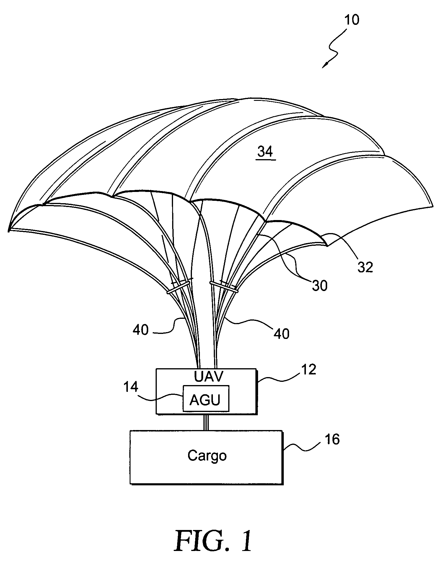
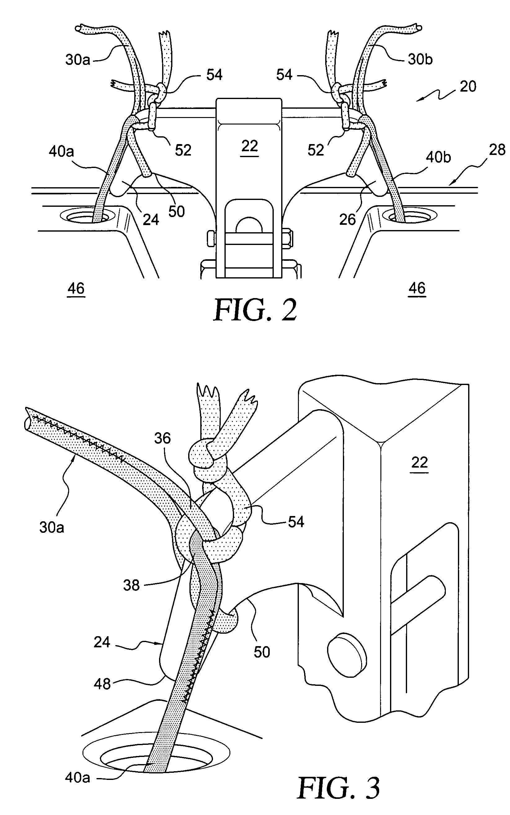
[0034]the present invention is shown in FIGS. 2 and 3. A deployment brake release system, generally designated by the reference numeral 20, is mounted on the rear of AGU 14 of a parachute system 10 such as that shown in FIG. 1. Shown in FIGS. 2 and 3 in a rigged, pre-deployment configuration, the deployment brake release system 20 includes a hook mount 22 having first and second hooks 22, 24 respectively mounted on the left and right sides of the frame 28 of the AGU. While the preferred embodiment includes left and right hooks, it is possible to construct the deployment brake release system with only a single hook.
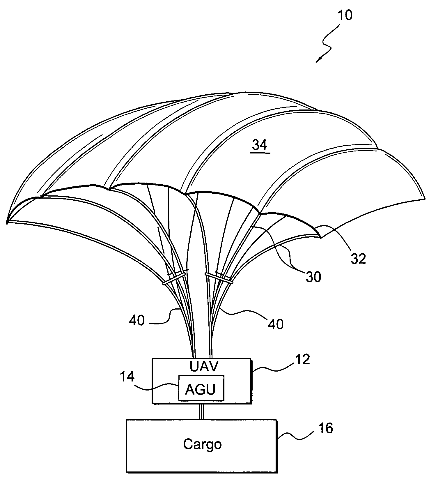
[0035]As is known, deployment brake release lines 30 are attached to the trailing edge 32 of a parachute canopy 34 during rigging to effect downward deflection of the edge 32 during initial inflation. The deployment brake release lines 30 are subsequently released to allow full inflation of the chute at the appropriate time and, in the case of the left and right outer brak...
second embodiment
[0041]the present invention especially useful for larger cargo parachute systems is shown in FIG. 4. Larger cargo parachute systems need additional brake lines to accommodate the greater total force on the canopy trailing edge and to maintain a better trim shape of the canopy control surfaces during deployment. In most cases, these additional brake lines are used to deflect the canopy only during deployment; they are not used to steer the parachute once steady state flight status has been achieved. Thus, while the release of a greater number of brake lines is required, generally only the last brake line released on each side, i.e., the outer brake lines, will ultimately act as steering brake lines to be controlled by the motors.
[0042]In the embodiment shown in FIG. 4, there is only one additional brake line on each side. (The third line shown is a so-called “lazy line” to be described later.) Hence, there are left inner and outer brake lines 60 and 62, respectively, and right inner ...
PUM
 Abstract
Description
Claims
Application Information
 - R&D
- Intellectual Property
- Life Sciences
- Materials
- Tech Scout
- Unparalleled Data Quality
- Higher Quality Content
- 60% Fewer Hallucinations
Browse by: Latest US Patents, China's latest patents, Technical Efficacy Thesaurus, Application Domain, Technology Topic, Popular Technical Reports.
© 2025 PatSnap. All rights reserved.Legal|Privacy policy|Modern Slavery Act Transparency Statement|Sitemap|About US| Contact US: help@patsnap.com


