High speed aerospace generator resilient mount, combined centering spring and squeeze film damper

a technology of aerospace generators and resilient mounts, applied in the direction of elastic bearings, rigid support of bearings, mechanical equipment, etc., can solve the problems of increasing the installation time of plurality of support rods, and achieving and maintaining the precision balan

Inactive Publication Date: 2010-01-19
HONEYWELL INT INC
View PDF18 Cites 28 Cited by
  • Summary
  • Abstract
  • Description
  • Claims
  • Application Information

AI Technical Summary

Problems solved by technology

Practically achieving and maintaining this precision balance can be difficult due to variations in the manufacture and assembly process.
If an unbalanced rotor is rotating for prolonged periods of time at one of its critical speeds, it may be damaged, even catastrophically.
Although the described assemblies may be used to provide the necessary damping, the positioning of the plurality of support rods increases installation time.
Although the described support may limit or damp out the vibrations occurring when the supported member passes through natural frequencies before reaching operating speed, the '574 patent design is complex, requires radial and axial space for implementation and can only be tuned during design for a particular application.

Method used


Image

  • High speed aerospace generator resilient mount, combined centering spring and squeeze film damper
  • High speed aerospace generator resilient mount, combined centering spring and squeeze film damper
  • High speed aerospace generator resilient mount, combined centering spring and squeeze film damper

Examples


example 1

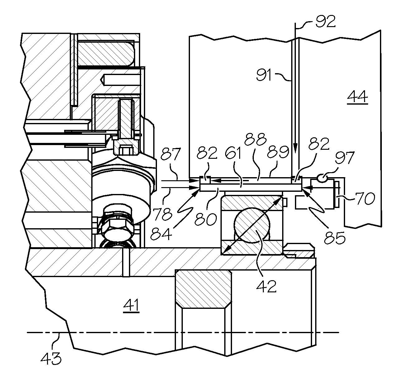
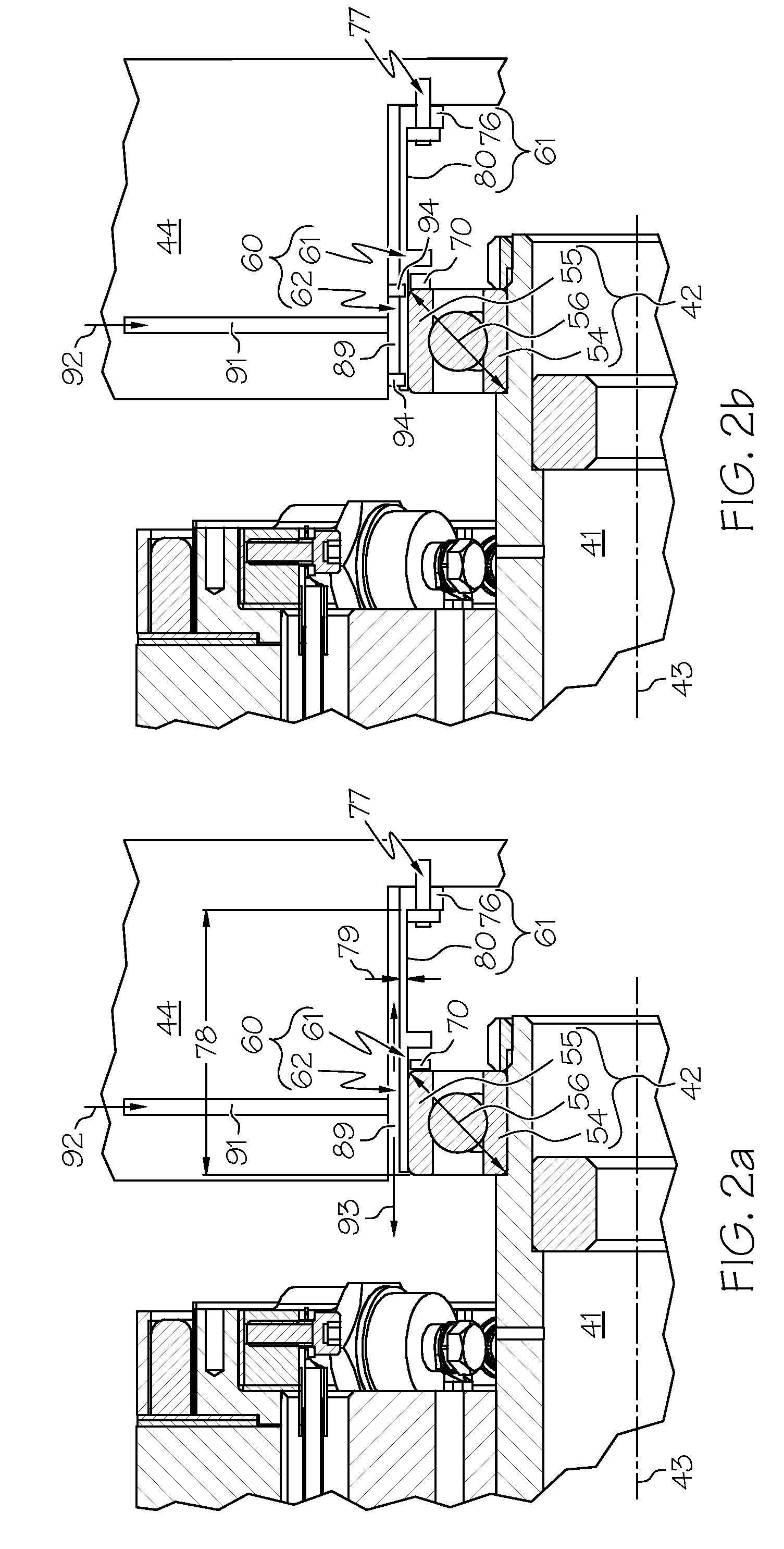
[0054]A spring member 61 having a tube spring design can be bolted to a support housing, as depicted in FIGS. 2a and 2b. In these embodiments, the inlet line 91 provides a center feed. The embodiment in FIG. 2a has an open ended mount and the embodiment in FIG. 2b includes two piston rings 94 to form a restricted ended mount. The embodiments in FIGS. 2a and 2b both include an axial spring 70 to provide axial loading to the bearing pair.

example 2

[0055]A spring member 61 having a tube spring design can be bolted to a support housing, as depicted in FIGS. 3a and 3b. In these embodiments, the inlet line 91 provides an end feed. The embodiment in FIG. 3a has an open ended mount and the embodiment in FIG. 3b has a recirculating mount. The embodiments in FIGS. 3a and 3b do not provide axial loading to the bearing pair, and the bearing pair is loaded by from a spring on the other bearing (not shown). An axial load may be provided by placement of a spring between a retainer 99 and the outer race 55 of the bearing 42. The retainer 99 may comprise a support structure fixed to the housing 44.

example 3

[0056]A spring member 61 having a tube spring design can be bolted to a support housing, as depicted in FIG. 4. In this embodiment, the spring member 61 is integral to the outer race of the bearing assembly 42. In this embodiment, the inlet line 91 provides a center feed. This embodiment includes two piston rings 94 to form a restricted ended mount. The embodiment in FIG. 4 does not provide axial loading to the bearing pair.


PUM


Abstract

A rotor mount assembly for an electrical machine, such as a high speed aerospace generator, comprises a spring having a simple annular structure together with an oil squeeze film damper (SFD). The spring is engineered to move the rotor critical speeds outside of the extremes of the operating speed range and the SFD damps out the rotor responses as the speed passes through these points.

Description

BACKGROUND OF THE INVENTION[0001]The present invention generally relates to electrical machines, such as high speed aerospace generators and motors, and, more particularly, to mounting assemblies that interface between the bearing assemblies of the rotor shaft and the support housing of the electrical machines.[0002]Aircraft systems include various types of rotating electrical machines, such as alternating current (AC) motors and generators of various designs. Generally, the electrical machine includes a rotor and a stator. The rotor is part of a rotating shaft assembly supported by bearings. The stator is part of a static assembly that supports the rotor. For current electrical machines, the bearings are directly mounted to the static structure, often referred to as the housing, or have a hydraulic damper between the bearing outer race and the housing mounting bore (see U.S. Pat. No. 6,747,383).[0003]If the machine is operated as a motor, electrical power is supplied to the stator ...

Claims


Application Information

Patent Timeline
Patent Type & Authority Patents(United States)
IPC IPC(8): F16C27/00
CPCF16C27/04F16C27/045F16C35/077F16F15/0237H02K5/24F16C2380/26
Inventor STOUT, DAVID E.BIRDI, BALWINDER S.DOWN, EDWARD M.MEACHAM, WALTER L.
Owner HONEYWELL INT INC
Why Eureka
Try Eureka