
Method and device for maintenance of high-voltage switchgear with voltage

a high-voltage switchgear and maintenance method technology, applied in the direction of air-break switch details, shields/guards preventing contact access, metal casing arrangements, etc., can solve the problems of unresolved solutions for maintenance of high-voltage switchgear in an installation, unsatisfactory cost for power companies, and affecting the safety of personnel

Inactive Publication Date: 2010-01-19
TRONDHEIM ENERGIVERK NETT AS +1
View PDF24 Cites 5 Cited by
  • Summary
  • Abstract
  • Description
  • Claims
  • Application Information

AI Technical Summary

Benefits of technology

"The invention provides a method and device for secure maintenance of high-voltage switchgears in an installation. The device includes specially formed screening plates to shield / insulate switchgears / phases from each other, and from the walls of the switchgear cell. The screening plates can be easily and securely arranged between the phases / switchgears by means of an insulated claw rod. The method also includes important checkpoints, marking safety distance, removing containment boom, arrangement of screening plates, connecting shunts to the connection points of the phases, measuring and control of the current load of the shunts, disconnecting / laying out the switchgears, maintenance and function test of switch, disconnection of shunts from the connection points, and replacing the containment boom. This method ensures full operation of the switchgear / installation during maintenance and the safety of personnel and equipment is ensured."

Problems solved by technology

It is related great danger for personnel working in connection with such installations.
Today, however no solutions exists which are related to maintenance of high-voltage switchgears in an installation, while the switchgear / installation is under operation, i.e. under voltage.
This is something that causes unnecessary costs for power companies, since the adjacent parts of the installation (network stations) must be reconnected to supply the network loop which is connected to the current part of the installation, which is to be maintained with voltage.
This results in increased labour costs and in some cases, also loss of incomes if the current distribution loop not can be supplied with energy via other parts of the installation (network stations).

Method used


Image

  • Method and device for maintenance of high-voltage switchgear with voltage
  • Method and device for maintenance of high-voltage switchgear with voltage
  • Method and device for maintenance of high-voltage switchgear with voltage

Examples


Embodiment Construction

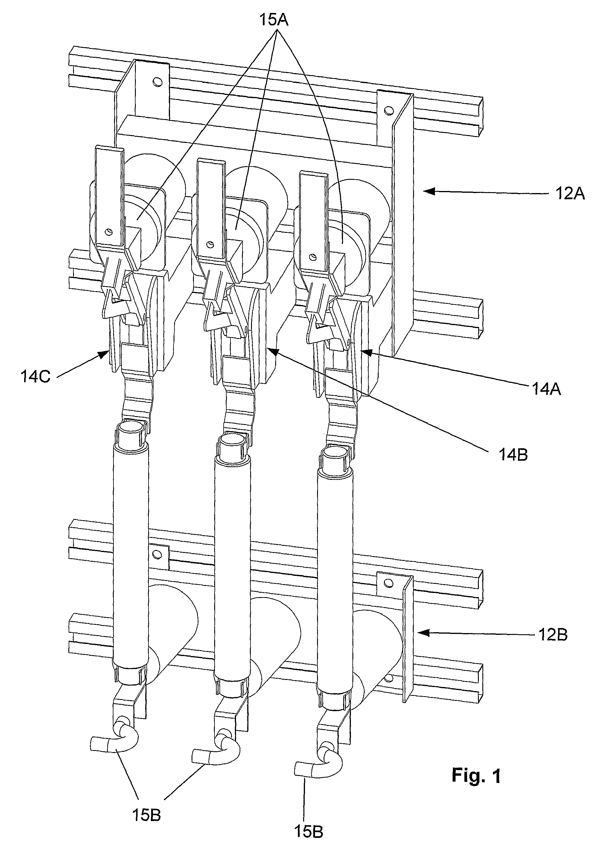
[0031]FIG. 1 shows a standard connection in a switchgear cell. A standard connection includes two switchgear brackets 12A and 12B, which are hangers and support for the screening plates. The connection further includes three phases 13A-C with each own fuse / switchgear 14A-C. Each phase 13A-C has upper 15A and lower 15B connection points, respectively, where the upper connection point 15A is a rail, while the lower 15B connection point is shaped as a projecting hook. This arrangement is the basis for maintenance, where maintenance needs to be performed in relation to switchgears / fuses 14A-14C.

[0032]As the arrangement is today, maintenance can not be performed while the switchgear / installation is under voltage / operation, something that will be possible by means of the invention.

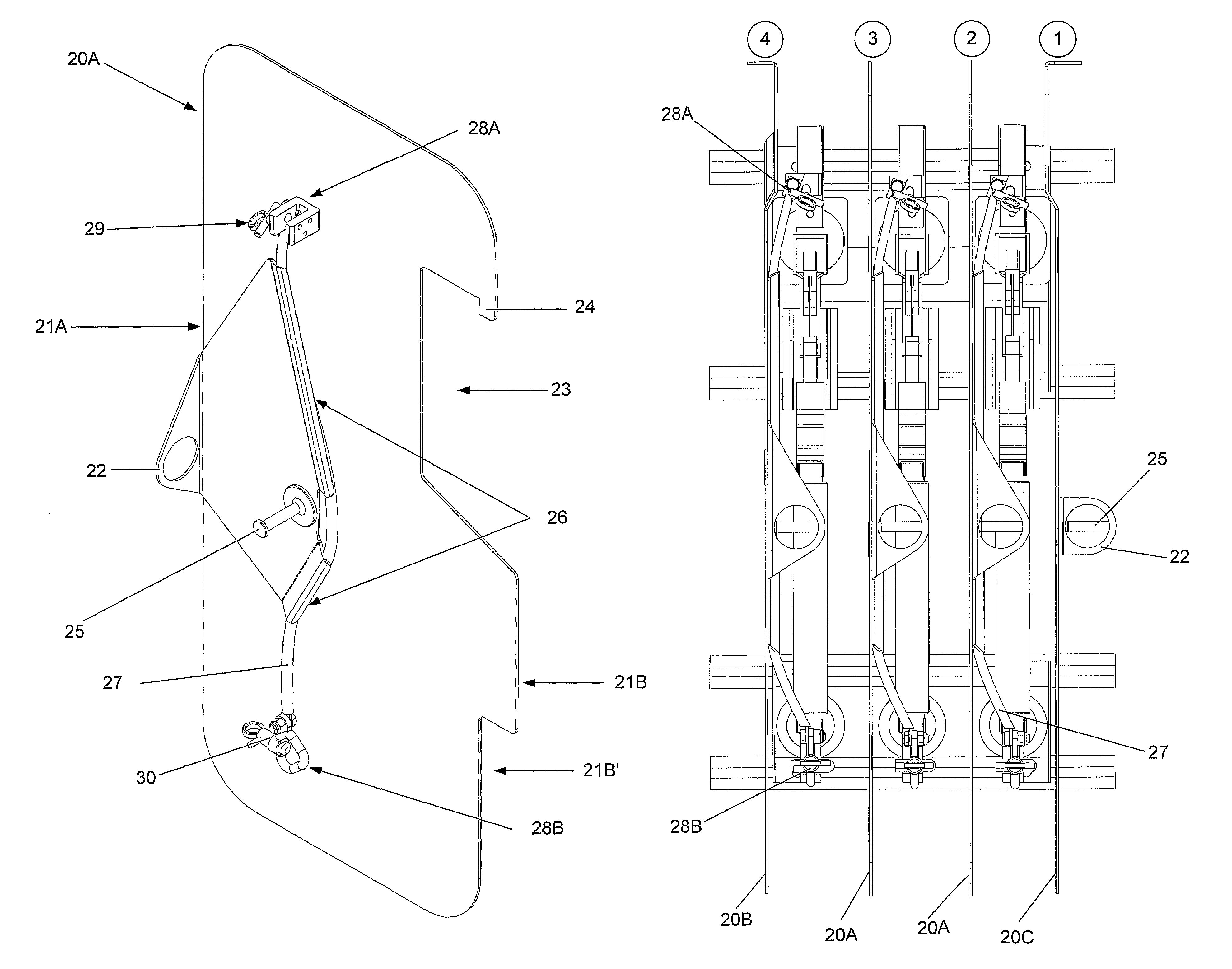
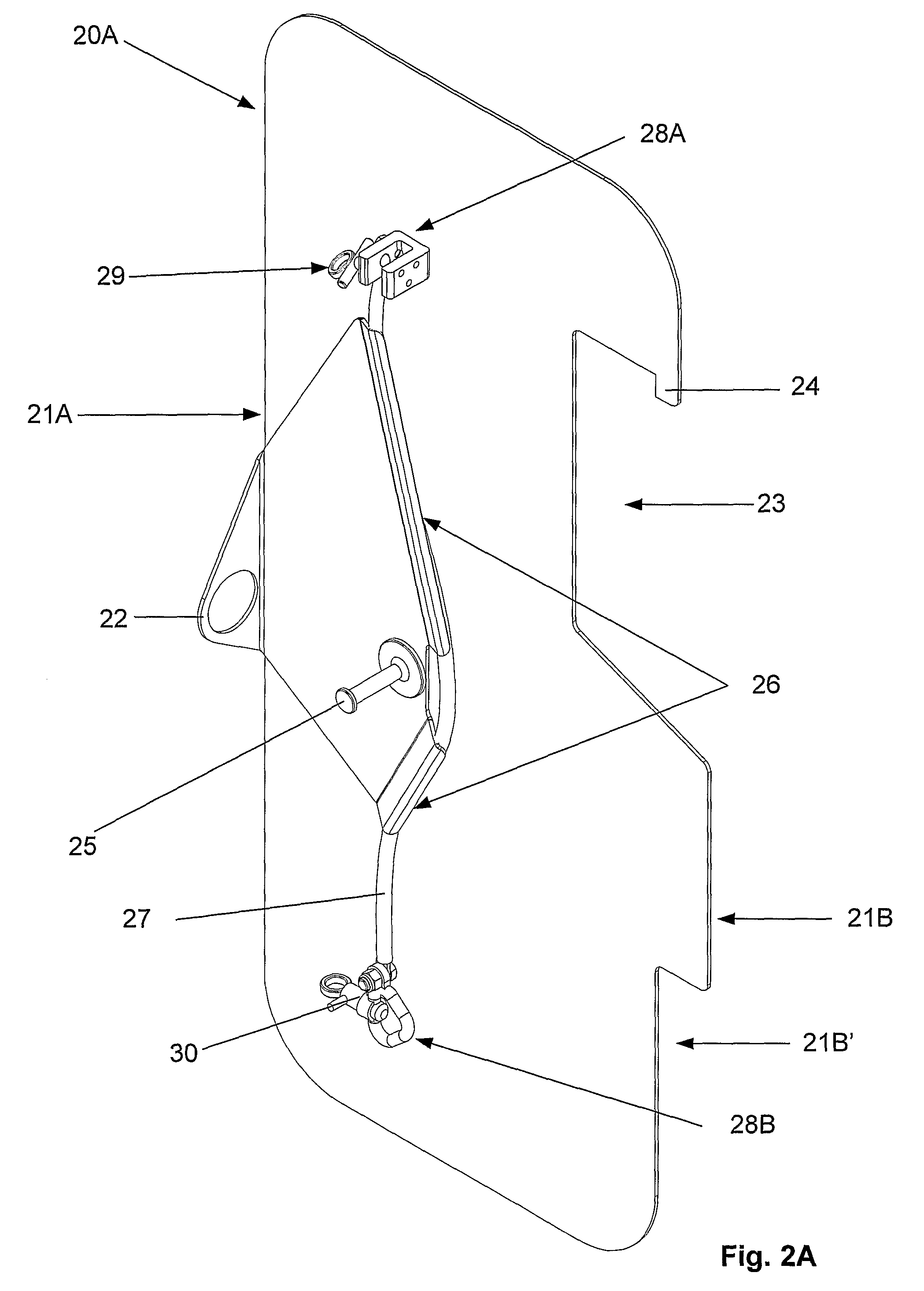
[0033]Referring now to FIGS. 2A-C, which shows different screening plates 20A-C, according to the invention, which are designed for use during maintenance when the network station is under voltage / operation. The...


PUM


Abstract

Method for maintenance of high-voltage switchgear / fuses in an installation, which method is performed while the switchgear / installation is under operation / voltage. It is further provided a device for carrying out the method, which device includes screening plates 20A-C, which screening plates are provided with maneuvring means 22 and 25, fastening means 23 and 24 for fastening of the screening plates to the switchgear cell / installation and means for disconnecting the switch 27, 28A-B.

Description

[0001]The invention relates to a device for maintenance of high-voltage switchgear, preferably diverter switch and disconnecting switch. The invention also relates to a method for performing safely maintenance of high-voltage switch gear with voltage.BACKGROUND[0002]Electrical network / installations include high-voltage switchgears, as an example in network stations, i.e. distributing stations which, usually by step-down transformation, supplies distribution nets with low voltage or which opposite transforms the voltage up. High-voltage is usually supplied to these network stations, which accordingly is transformed down to the correct voltage which is distributed out to the users, i.e. households and companies. All such installations include equipment which needs maintenance. Examples of such equipment are diverter switch and disconnecting switch which are used to connect / disconnect the different distribution loops that a transformer is connected to. Today, different solutions for cl...

Claims


Application Information

Patent Timeline
Patent Type & Authority Patents(United States)
IPC IPC(8): H01H31/02
CPCH02B3/00H02B1/14H02B11/24H02B13/02
Inventor MIKKELSEN, PER STEINARSOLUM, GEIR
Owner TRONDHEIM ENERGIVERK NETT AS
Learn More