Actuator capable of driving with large rotational angle or large deflection angle

a technology of actuators and rotating parts, applied in the field of actuators, can solve the problems of increasing manufacturing costs, difficult to miniaturize the size of the apparatus in which the polygon mirror is used, and difficult to rotate the polygon mirror at much higher speed, so as to prevent the amplitude of each of the driving parts, the effect of enlarge the rotational angle (deflection angle) of the movable portion

Inactive Publication Date: 2010-01-19
SEIKO EPSON CORP
View PDF28 Cites 5 Cited by
  • Summary
  • Abstract
  • Description
  • Claims
  • Application Information

AI Technical Summary

Benefits of technology

[0018]This makes it possible to enlarge a rotational angle (deflection angle) of the movable portion. In addition, since movable portion is provided between the pair of driving portions, it is possible to operate the movable portion with a larger torque.
[0045]Thus, it is possible to enlarge the rotational angle (deflection angle) of the movable portion while preventing the amplitude of each of the driving portions.

Problems solved by technology

However, there is a problem in that it is difficult to rotate the polygon mirror at much higher speed than the speed available at the present.
Further, although a larger motor is required in order to rotate the polygon mirror at higher speed, use of such a larger motor gives rise to a problem in that it is difficult to miniaturize the size of an apparatus in which the polygon mirror is used.
Furthermore, use of such a polygon mirror gives rise to another problem in that the structure of the apparatus becomes necessarily complicated, thus leading to increased manufacturing cost.
Namely, such a single-degree-of-freedom torsional vibrator described above involves a problem in that it is difficult to achieve both of low-voltage driving and large displacement.

Method used


Image

  • Actuator capable of driving with large rotational angle or large deflection angle
  • Actuator capable of driving with large rotational angle or large deflection angle
  • Actuator capable of driving with large rotational angle or large deflection angle

Examples


Embodiment Construction

[0057]Hereinafter, a preferred embodiment of an actuator according to the invention will be described with reference to the appended drawings.

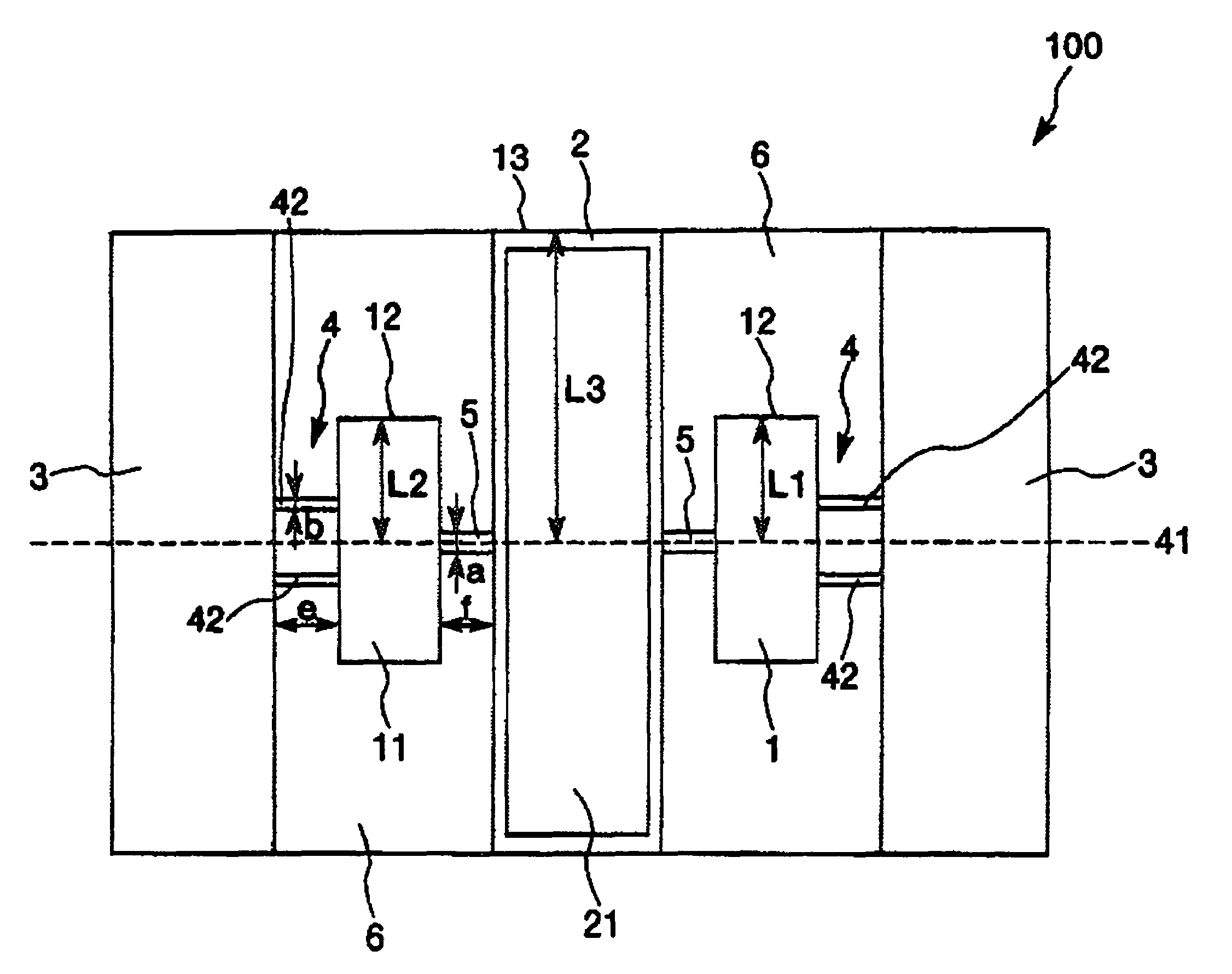
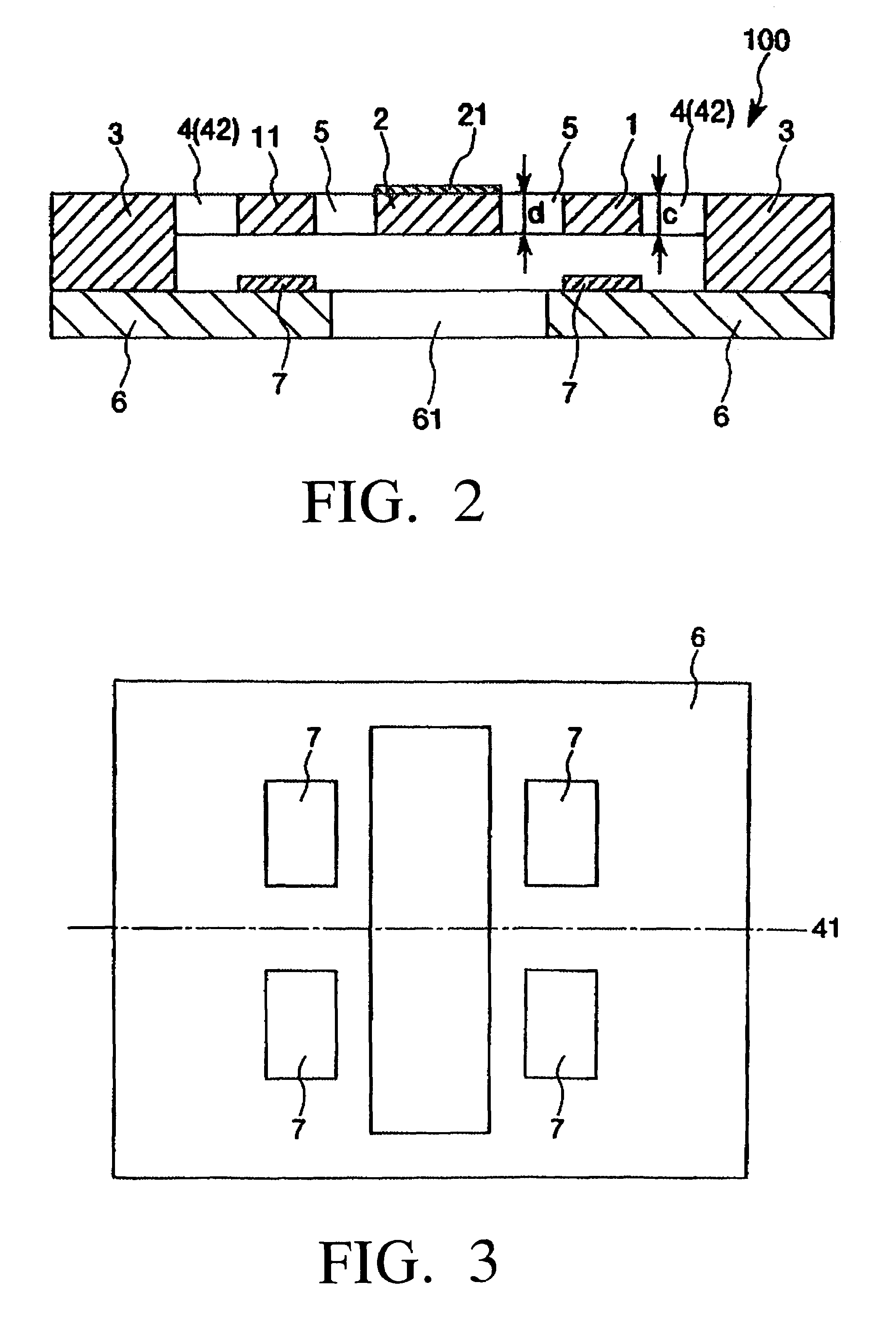
[0058]First, an embodiment of the actuator according to the invention will be described. FIG. 1 is a plan view which shows an embodiment of the actuator according to the invention. FIG. 2 is a cross-sectional view taken along line A-A in FIG. 1. FIG. 3 is a plan view which shows the arrangement of the electrodes of the actuator-shown in FIG. 1. FIG. 4 is a drawing which shows an example of the alternating voltage to be applied to the actuator shown in FIG. 1. FIG. 5 is a graph which shows the frequency of an alternating voltage applied and the resonance curves of the driving portions and the movable portion. In the following description using FIGS. 1 and 3, for convenience of description, it is to be noted that the upper side, the lower side, the right side and the left side in FIGS. 1 and 3 will be referred to as the “upper side”, “lower side...


PUM


Abstract

An actuator 100 includes: a pair of driving portions 1, 11 spaced apart from each other; a movable portion 2 provided between the pair of driving portions 1, 11; a pair of supporting portions 3, 3 for supporting the pair of driving portions 1, 11 and the movable portion 2; a pair of first elastic connecting portions 4, 4 which respectively connect the pair of driving portions 1, 11 to the pair of supporting portions 3, 3 so that each of the driving portions 1, 11 can rotate with respect to the supporting portions 3, 3; and a pair of second elastic connecting portions 5, 5 which respectively connect the movable portion 2 to the pair of driving portions 1, 11 so that the movable portion 2 can rotate in accordance with the rotation of the pair of driving portions 1, 11. In this case, each of the pair of driving portions 1, 11 rotates around a rotation central axis 41 of the actuator 100 by application of an alternating voltage, whereby the movable portion 2 rotates around the rotation central axis 41 of the actuator 100. Further, the torsional rigidity of each of the first elastic connecting portions 4, 4 is larger than that of each of the second elastic connecting portions 5, 5.

Description

CROSS-REFERENCE TO RELATED APPLICATION[0001]This application claims priority to Japanese Patent Application No. 2004-363608 filed Dec. 15, 2004, which is hereby expressly incorporated by reference herein in its entirety.BACKGROUND OF THE INVENTION[0002]1. Field of the Invention[0003]The present invention relates to an actuator, and in particular relates to an actuator of the type employing a two-degree-of-freedom vibration system.[0004]2. Description of the Prior Art[0005]There is known a polygon mirror (rotary polyhedron) as an actuator provided in laser printers, for example. In such a printer, in order to achieve higher-resolution and higher-quality printed output as well as higher-speed printing, it is necessary to rotate the polygon mirror at higher speed. Currently, an air bearing is used to rotate the polygon mirror at high speed with stability. However, there is a problem in that it is difficult to rotate the polygon mirror at much higher speed than the speed available at th...

Claims


Application Information

Patent Timeline
Patent Type & Authority Patents(United States)
IPC IPC(8): G02B26/08H02N1/00
CPCG02B26/0841H02N1/006
Inventor YODA, MITSUHIROITO, HIROKAZU
Owner SEIKO EPSON CORP
Why Eureka
Try Eureka