

Thin flash-hard-drive with two-piece casing
a two-piece, flash drive technology, applied in the direction of electrical apparatus casing/cabinet/drawer, coupling device connection, instruments, etc., can solve the problem of unsecure information transfer
- Summary
- Abstract
- Description
- Claims
- Application Information
AI Technical Summary
Benefits of technology
Problems solved by technology
Method used
Image

Examples
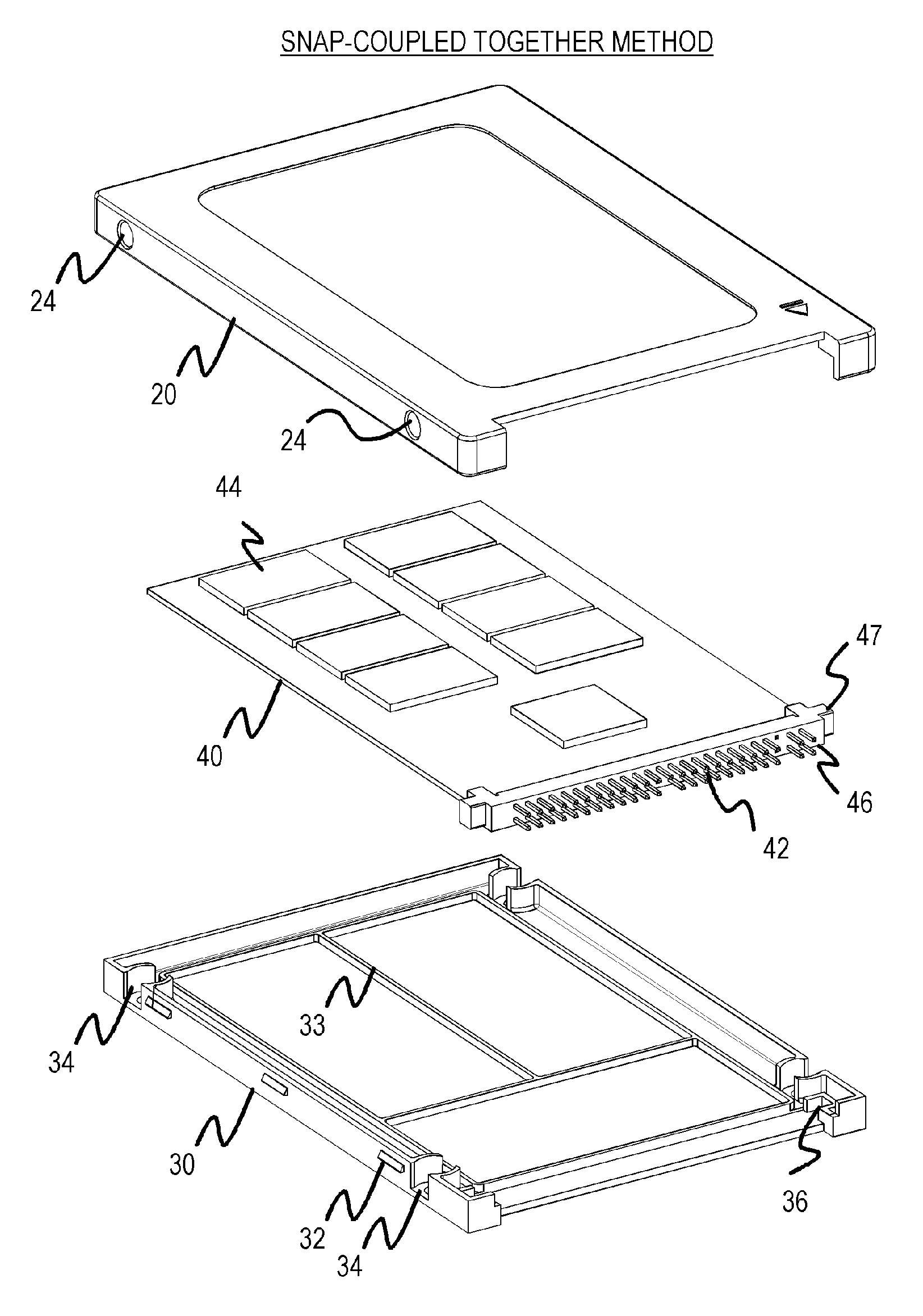
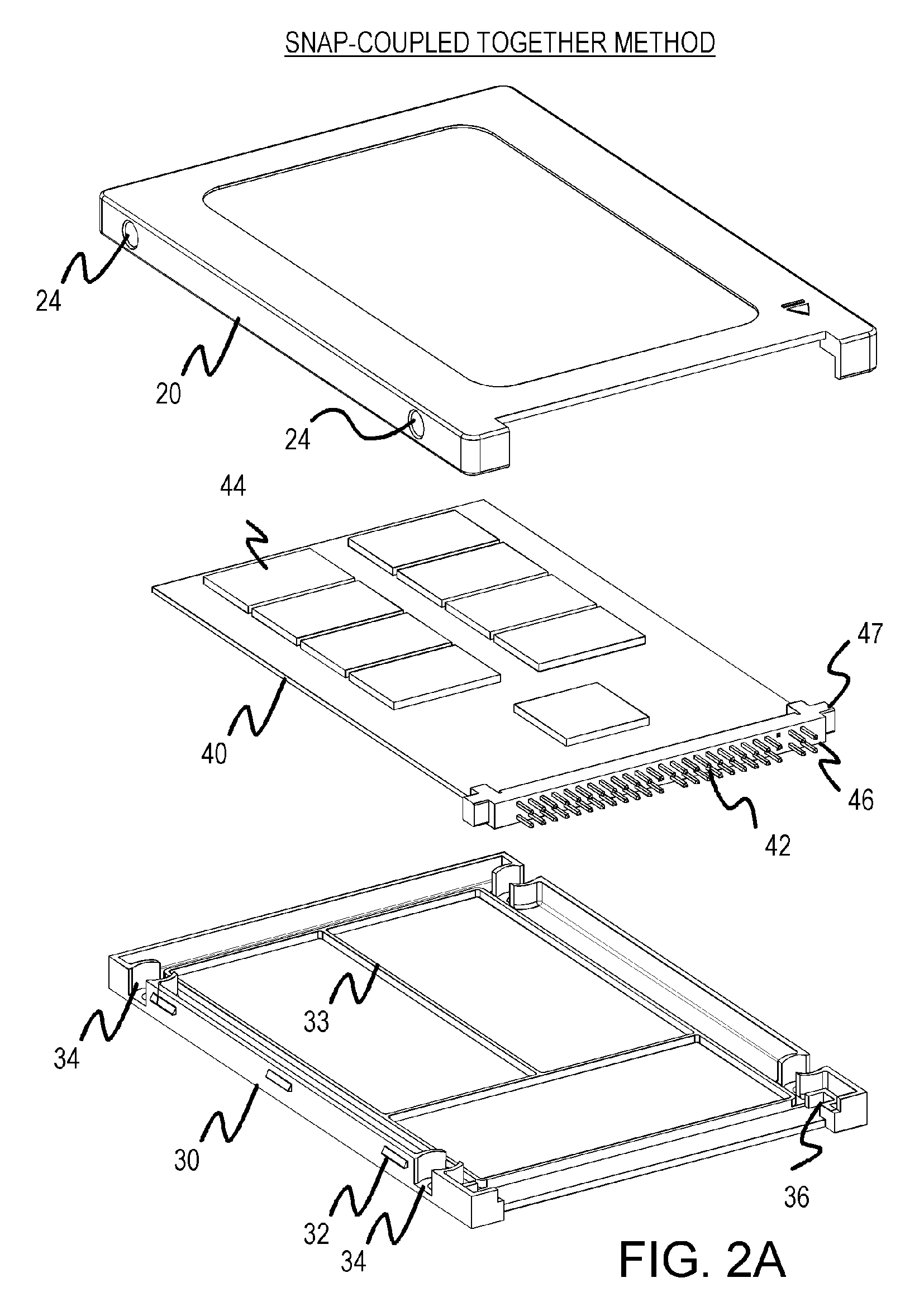
case 30
[0021]Lower case 30 also has center lines 33 that are raised ridges. Center lines 33 fits between rows of chips 44 when PCBA 40 is fitted into lower case 30. Center lines 33 can be sufficiently tall to reach the lower surface of the circuit board in PCBA 40 to add support of the final assembled flash drive. Center lines 33 can thus prevent the middle of lower case 30 from flexing or dimpling inward when a user pinches together the centers of upper case 20 and lower case 30 of the assembled device. Center lines 33 can thus give the finished device a more rugged and solid feel in the user's hands, increasing the user's perception of quality of the device.
case 20
[0022]Upper case 20 is then fitted into the sub-assembly of PCBA 40 and lower case 30. Four alignment pegs 24 on upper case 20 fit into four alignment sockets 34 that are formed on the sides of lower case 30 to align upper case 20 during assembly. As upper case 20 is pressed downward during assembly, alignment pegs 24 slide downward into alignment sockets 34. As upper case 20 reaches the fully-inserted position during assembly, locking tabs 32 formed on the outer edges of lower case 30 fit and snap into engagement slots 22 (see FIG. 2C) on upper case 20, locking upper case 20 into lower case 30.
[0023]FIG. 2B shows a top view of upper case 20, while FIG. 2C shows a bottom view of upper case 20. Upper case 20 can also have center lines 23 that fit between chips 44 on PCBA 40. Center lines 23 can increase support of upper case 20, in a manner similar to that described for center lines 33 on lower case 30. Engagement slots 22 receive locking tabs 32 to snap-couple together upper case 20...
case 50
[0032]Upper case 50 is then fitted over the sub-assembly of PCBA 40 and lower case 70. Four alignment cutouts 52 on upper case 50 fit around four alignment tabs 72 that are formed on the sides of lower case 70 to align upper case 50 during assembly. As upper case 50 is pressed downward during assembly, alignment tabs 72 fit inside alignment cutouts 52.
[0033]The un-bonded assembly can then be placed in a jig or fixture for ultrasonic bonding. Upper case 50 is rapidly vibrated with respect to lower case 70 by the ultrasonic bonding apparatus while being pressed together. This rapid movement creates friction where upper case 50 touches lower case 70. This localized friction quickly heats up the contacting parts of upper case 50 and lower case 70. In particular, alignment tabs 72 touch the inside of alignment cutouts 52, causing localized heating. This heating eventually melts alignment tabs 72 into alignment cutouts 52, bonding them together.
[0034]FIG. 5B shows a top view of upper case...
PUM
 Abstract
Description
Claims
Application Information