
Bicycle crank assembly

a crank assembly and bicycle technology, applied in the direction of bearings, shafts and bearings, vehicle components, etc., can solve the problems of complex bearing adjustment work, fixed bolts cannot be used when, crank assembly cannot be rigidly fixed to the crank axle, etc., to simplify the work of adjusting bearing play

Inactive Publication Date: 2010-01-26
SHIMANO INC
View PDF18 Cites 26 Cited by
  • Summary
  • Abstract
  • Description
  • Claims
  • Application Information

AI Technical Summary

Benefits of technology

The present invention provides a bicycle crank assembly that simplifies the process of adjusting bearing play when the crank assembly is mounted on the crank axle. This is achieved by including a crank body with a crank axle mounting part, an adjustment member with a tube-shaped fixing part and a contact part, and a rotation operation part. The adjustment member can be easily rotated relative to the crank body by screwing the second screw part into the first screw part. The bearing play can be adjusted by turning the adjustment member, and the adjustment member can be locked in place using a clamping bolt or a slit. The crank assembly includes a crank axle mounting part with a crank axle receiving hole that non-rotatably engages the crank axle. The contact part can be designed to press the inner ring of the bearing inwardly. The rotation operation part makes it easy to turn the adjustment member by hand. These features simplify the process of adjusting bearing play and make the crank assembly easier to mount and adjust.

Problems solved by technology

When a taper is used for mounting and the fixed bolt that screws into the crank axle is not completely tightened, a gap is created between the crank assembly and the crank axle, such that the crank assembly can not be rigidly fixed to the crank axle.
Therefore, a fixed bolt can not be used when adjusting the crank assembly for bearing play.
In this case, the work of bearing adjustment becomes complicated since removing the fixed bolt and crank assembly must be repeated to add and subtract the shims when changing gap using shims during bearing play adjustment.

Method used


Image

  • Bicycle crank assembly
  • Bicycle crank assembly
  • Bicycle crank assembly

Examples


second embodiment

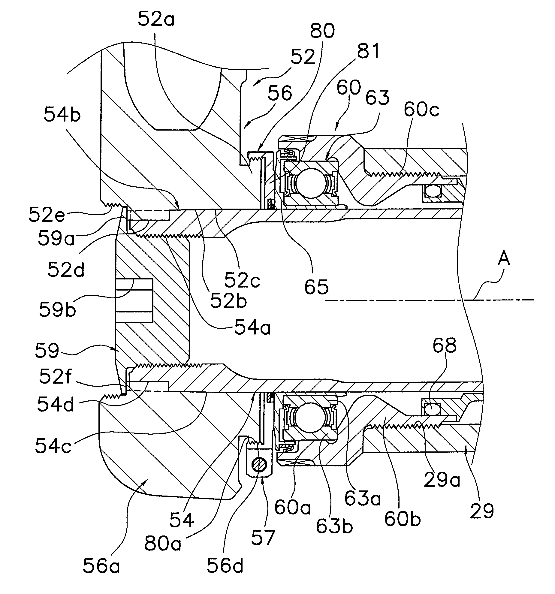
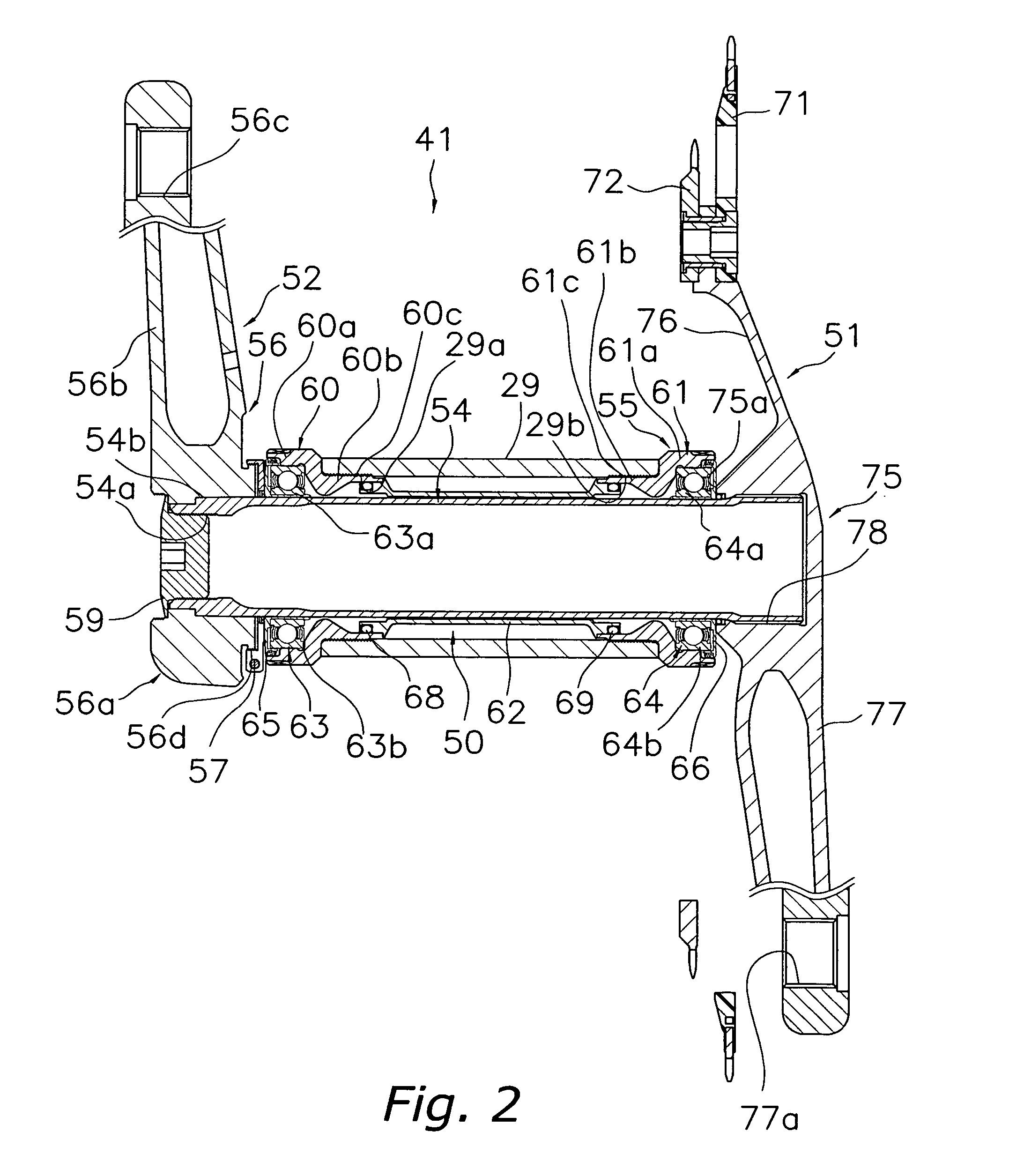
[0056]Referring now to FIGS. 6 and 7, a modified left crank 152 and an adjustment member 157 are illustrated in accordance with a second illustrated embodiment. The left crank 152 and the adjustment member 157 are installed on the crank axle 54 in the same manner as the first illustrated embodiment. In view of the similarity between the first and second illustrated embodiments, the parts of the second illustrated embodiment that are identical to the parts of the first illustrated embodiment will be given the same reference numerals as the parts of the first illustrated embodiment. Moreover, the descriptions of the parts of the second illustrated embodiment that are identical to the parts of the first illustrated embodiment may be omitted for the sake of brevity.

[0057]As seen in FIG. 6, for example, the left crank 152 has a hollow left crank body 56 that basically includes a crank axle mounting part 156a, an arm part (same as the first illustrated embodiment) and a pedal mounting par...


PUM


Abstract

A bicycle crank assembly is configured to simplify the work required to adjust the bearing play by the crank assembly when the crank assembly is mounted. The bicycle crank assembly has a left crank that is mounted on a crank axle of the bicycle, and is provided with a crank body and an adjustment member. The crank body includes a crank axle mounting part non-rotatably mounting to one end of the crank axle, an arm part extending from the crank axle mounting part, a pedal mounting part for mounting the pedal and provided at the tip of the arm part, and a male screw part formed on the crank axle mounting part. The adjustment member includes a tubular part having a female screw part into which the male screw part is screwed, and a contact part formed at one end of the tubular part and capable of contacting the bearing supporting the crank axle.

Description

CROSS-REFERENCE TO RELATED APPLICATIONS[0001]This application claims priority under 35 U.S.C. § 119 to Japanese Patent Application No. 2005-260374, filed Sep. 8, 2005. The entire disclosure of Japanese Patent Application No. 2005-260374 is hereby incorporated herein by reference.BACKGROUND OF THE INVENTION[0002]1. Field of the Invention[0003]This invention generally relates to a bicycle crank assembly. More specifically, the present invention relates to a bicycle crank assembly mounted on a bicycle crank axle.[0004]2. Background Information[0005]Bicycling is becoming an increasingly more popular form of recreation as well as a means of transportation. Moreover, bicycling has become a very popular competitive sport for both amateurs and professionals. Whether the bicycle is used for recreation, transportation or competition, the bicycle industry is constantly improving the various components of the bicycle. One component that has been extensively redesigned is the bicycle crank assem...

Claims


Application Information

Patent Timeline
Patent Type & Authority Patents(United States)
IPC IPC(8): B62M3/00F16C13/00F16C9/00
CPCB62M3/003Y10T74/2164
Inventor SHIRAISHI, SHINGOYAMANAKA, MASAHIROTATSUMI, TAKUJI
Owner SHIMANO INC
Learn More