
Cable tightening device with a base having a lower cost of fabrication

Inactive Publication Date: 2010-01-26
CHANG WEN CHENG
View PDF16 Cites 30 Cited by
  • Summary
  • Abstract
  • Description
  • Claims
  • Application Information

AI Technical Summary

Benefits of technology

[0010]The primary objective of the present invention is to provide a cable tightening device with a base having a lower cost of fabrication. Another objective of the present invention is to provide a cable tightening device, wherein the base of the fixed unit is integrally combined with the holding member without having to provide a bolt and a nut, thereby saving the price of material and thereby decreasing the costs of fabrication.
[0011]A further objective of the present invention is to provide a cable tightening device, wherein the holding member is integrally combined with the base of the fixed unit by punching without having to mount the holding member on the base of the fixed unit in a manual manner, thereby facilitating assembly of the cable tightening device.
[0012]A further objective of the present invention is to provide a cable tightening device, wherein the holding member is integrally combined with the base of the fixed unit by punching so that the holding member will not detach from the base of the fixed unit, thereby facilitating operation of the cable tightening device.

Problems solved by technology

However, it is necessary to provide the bolt 63 and the nut 64 for mounting the extension strap and the snapping hook, thereby increasing the costs of fabrication.
In addition, it is necessary to mount the bolt 63 and the nut 64 on the base 61 of the fixed unit 60, thereby greatly causing inconvenience in assembly of the cable tightening device.
Further, the nut 64 is easily unscrewed from the bolt 63 during a long-term utilization, thereby causing inconvenience in operation of the cable tightening device.

Method used


Image

  • Cable tightening device with a base having a lower cost of fabrication
  • Cable tightening device with a base having a lower cost of fabrication
  • Cable tightening device with a base having a lower cost of fabrication

Examples


Embodiment Construction

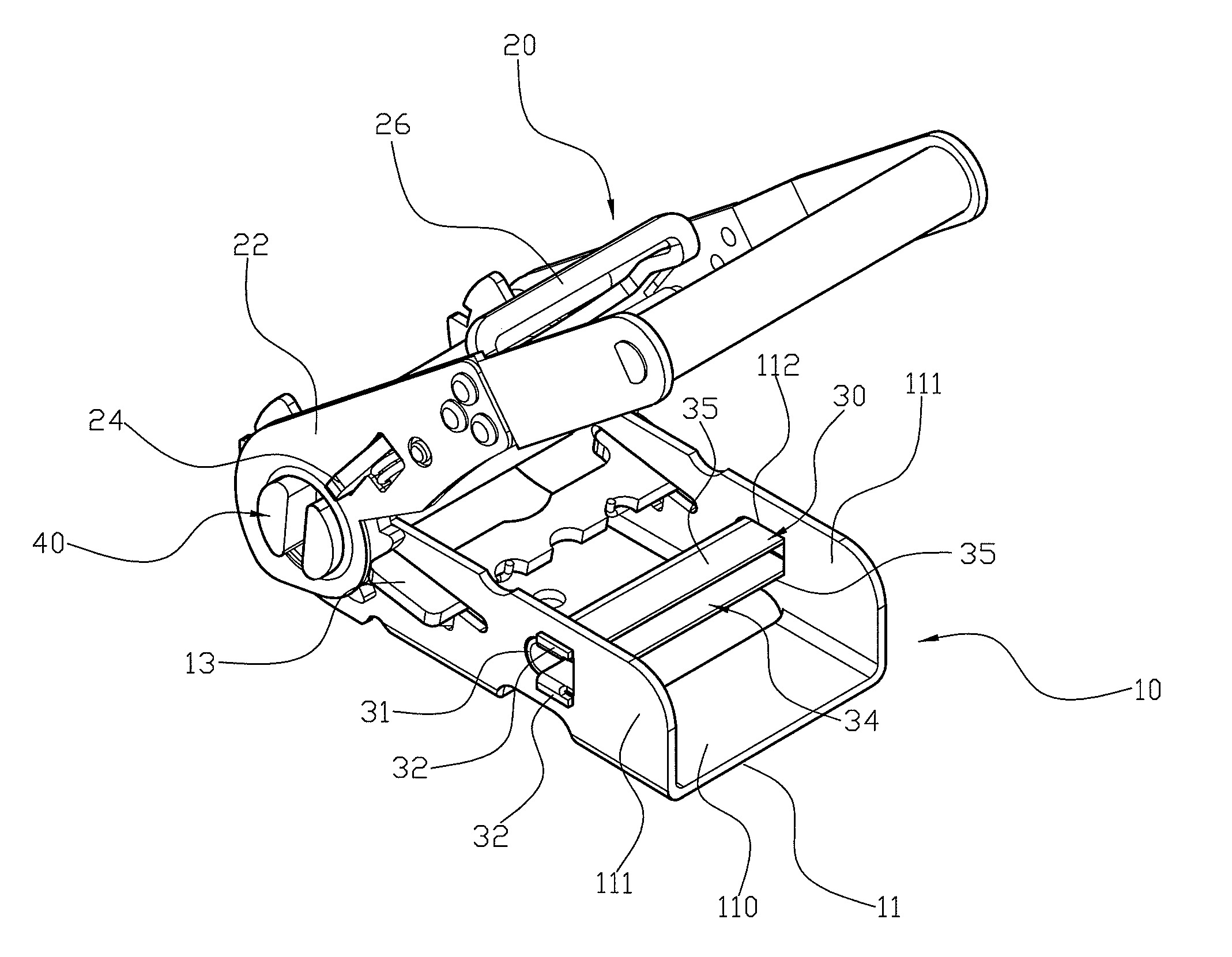
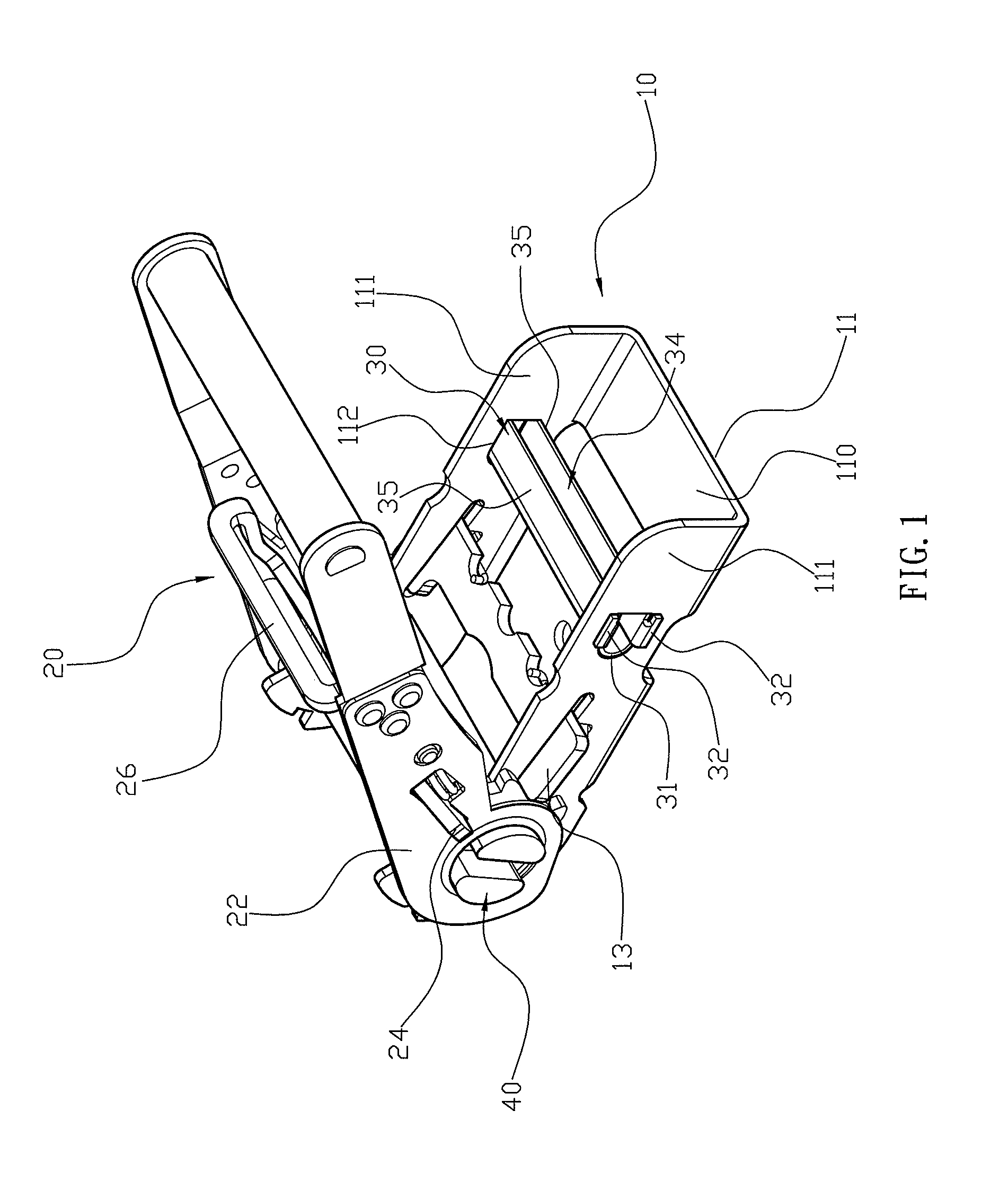
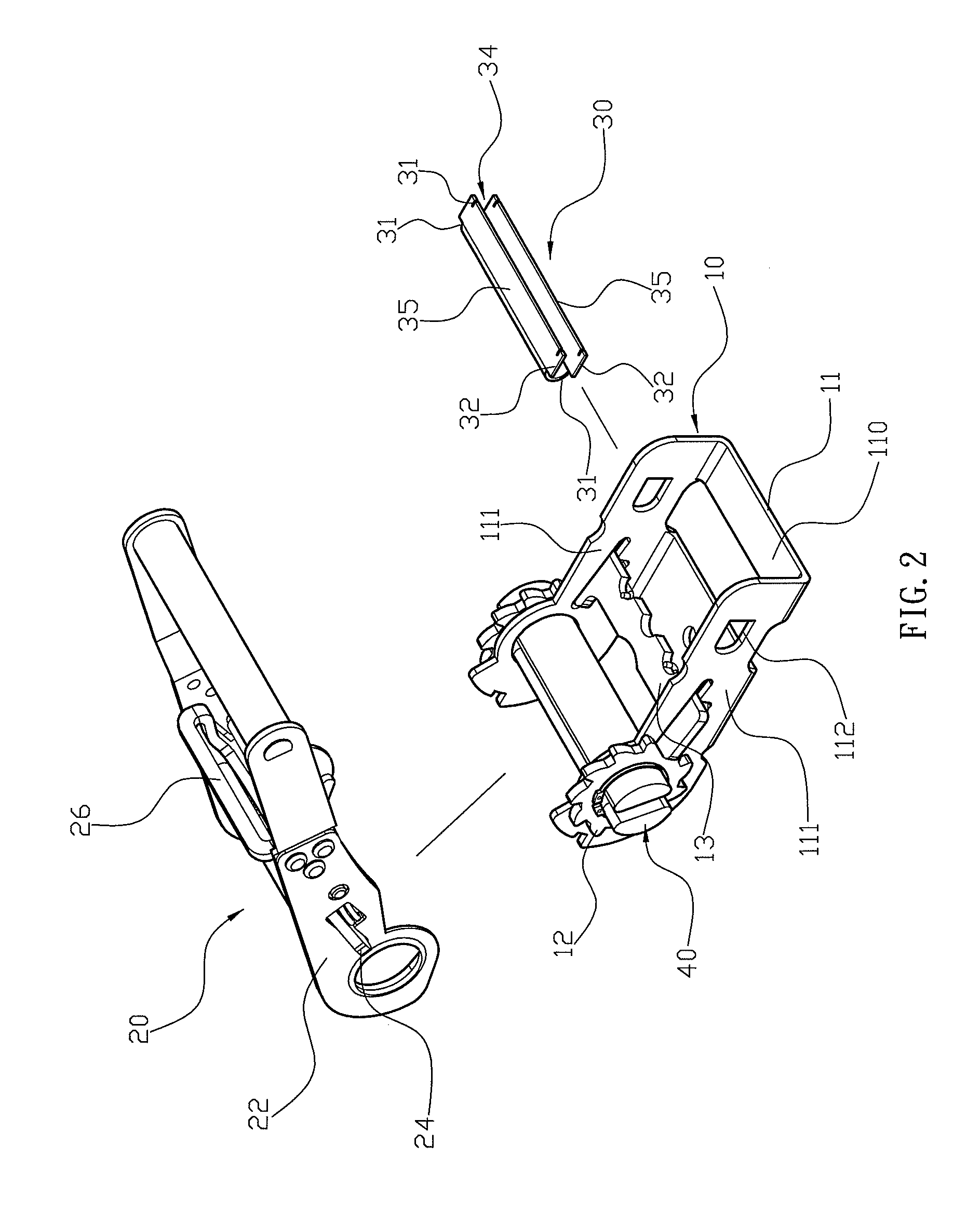
[0022]Referring to the drawings and initially to FIGS. 1 and 2, a cable tightening device in accordance with the preferred embodiment of the present invention comprises a fixed unit 10 including a base 11, a rotation member 40 rotatably mounted on a first end of the base 11 of the fixed unit 10 to wind and unwind a cable (not shown) by rotation of the rotation member 40, a movable unit 20 including a movable member 22 rotatably mounted on the rotation member 40 and movable relative to the base 11 of the fixed unit 10 to drive the rotation member 40 to rotate relative to the fixed unit 10 in a oneway direction, and a holding member 30 secured on a second end of the base 11 of the fixed unit 10.

[0023]The fixed unit 10 further includes two opposite ratchet wheels 12 secured on two opposite ends of the rotation member 40 to rotate the rotation member 40, and a stop plate 13 movably mounted on the base 11 and releasably engaged with the ratchet wheels 12 to allow the ratchet wheels 12 to...


PUM

PropertyMeasurementUnit
Shapeaaaaaaaaaa

Abstract

A cable tightening device includes a fixed unit including a base, a rotation member rotatably mounted on a first end of the base, a movable unit including a movable member rotatably mounted on the rotation member and movable relative to the base, and a holding member secured on a second end of the base. Thus, the base of the fixed unit is integrally combined with the holding member without having to provide a bolt and a nut, thereby decreasing the costs of fabrication. In addition, the holding member is integrally combined with the base of the fixed unit by punching so that the holding member will not detach from the base of the fixed unit, thereby facilitating operation of the cable tightening device.

Description

BACKGROUND OF THE INVENTION[0001]1. Field of the Invention[0002]The present invention relates to a cable tightening device and, more particularly, to a cable tightening device for tightening or loosening a cable so as to bind or release a cargo.[0003]2. Description of the Related Art[0004]A cable tightening device is mounted on a wheeled vehicle having a larger size, such as a truck or the like, to tighten a cable which is wound around a cargo so as to tighten the cargo.[0005]A conventional cable tightening device in accordance with the prior art shown in FIG. 8 comprises a fixed unit 60 including a base 61, a rotation member 80 rotatably mounted on the base 61 of the fixed unit 60 to wind and unwind a cable (not shown) by rotation of the rotation member 80, and a movable unit 70 including a movable member 71 rotatably mounted on the rotation member 80 and movable relative to the base 61 of the fixed unit 60 to drive the rotation member 80 to rotate relative to the fixed unit 60 in ...

Claims


Application Information

Patent Timeline
IPC IPC(8): B21F9/00
CPCB25B25/00B60P7/083Y10T24/2113Y10T24/2117Y10T24/2175
Inventor CHANG, WEN-CHENG
Owner CHANG WEN CHENG
Learn More