Conveying member, especially rotor or stator, for conveying a flowable, preferably gaseous medium

a technology of conveying member and flowable medium, which is applied in the direction of positive displacement liquid engine, piston pump, liquid fuel engine, etc., can solve the problems of difficult transportation of noise in the medium being conveyed, i.e., air, and achieve the effect of further reducing the generation of characteristic noise occurring during operation

Inactive Publication Date: 2010-01-26
EBERSPAECHER CLIMATE CONTROL SYST GMBH & CO KG
View PDF13 Cites 4 Cited by
  • Summary
  • Abstract
  • Description
  • Claims
  • Application Information

AI Technical Summary

Benefits of technology

[0006]The object of the present invention is to provide a conveying member, especially a rotor or a stator, for conveying a flowable medium, by which conveying member the generation of the characteristic noise occurring during operation can be further reduced.
[0008]It is elementary in the present invention that a markedly better noise quality can be achieved compared with a statistical circumferential distribution with a plurality of any desired circumferential distances due to the transition from a distribution of the blades that is a statistical distribution concerning the mutual circumferential distance, i.e., in principle, from the statistical selection of the mutual circumferential distance from any desired, nevertheless limited range of circumferential distances, to only two possible circumferential distances at least in a group of blades.
[0009]It is advantageous in this connection for the first circumferential distance and the second circumferential distance to occur at least twice in the group of blades, preferably if the circumferential distance of a blade from a blade directly following it in the circumferential direction is either the first circumferential distance or the second circumferential distance for all blades at the conveying member. However, a markedly improved noise quality can also be achieved in comparison to the positioning of the blades with a plurality of different circumferential distances from one another already if the group of blades comprises at least half the blades provided at the conveying member or if there is only one blade for which the circumferential distance between it and the blade directly following it in the circumferential direction is not the first circumferential distance and also not the second circumferential distance for only one blade.
[0012]To make it possible to set a condition for the first circumferential distance and the second circumferential distance in a simple manner especially also when the number of blades is taken into account, it is proposed, furthermore, that the first circumferential distance and the second circumferential distance be represented as an angular distance by:first circumferential distance (a)=α0−βsecond circumferential distance (b)==α0+βin which:

Problems solved by technology

To reduce the perceptibility of this tone or such noises, mufflers are frequently used to make it difficult to transport the noise in the medium being conveyed, i.e., the air.

Method used


Image

  • Conveying member, especially rotor or stator, for conveying a flowable, preferably gaseous medium
  • Conveying member, especially rotor or stator, for conveying a flowable, preferably gaseous medium
  • Conveying member, especially rotor or stator, for conveying a flowable, preferably gaseous medium

Examples


Embodiment Construction

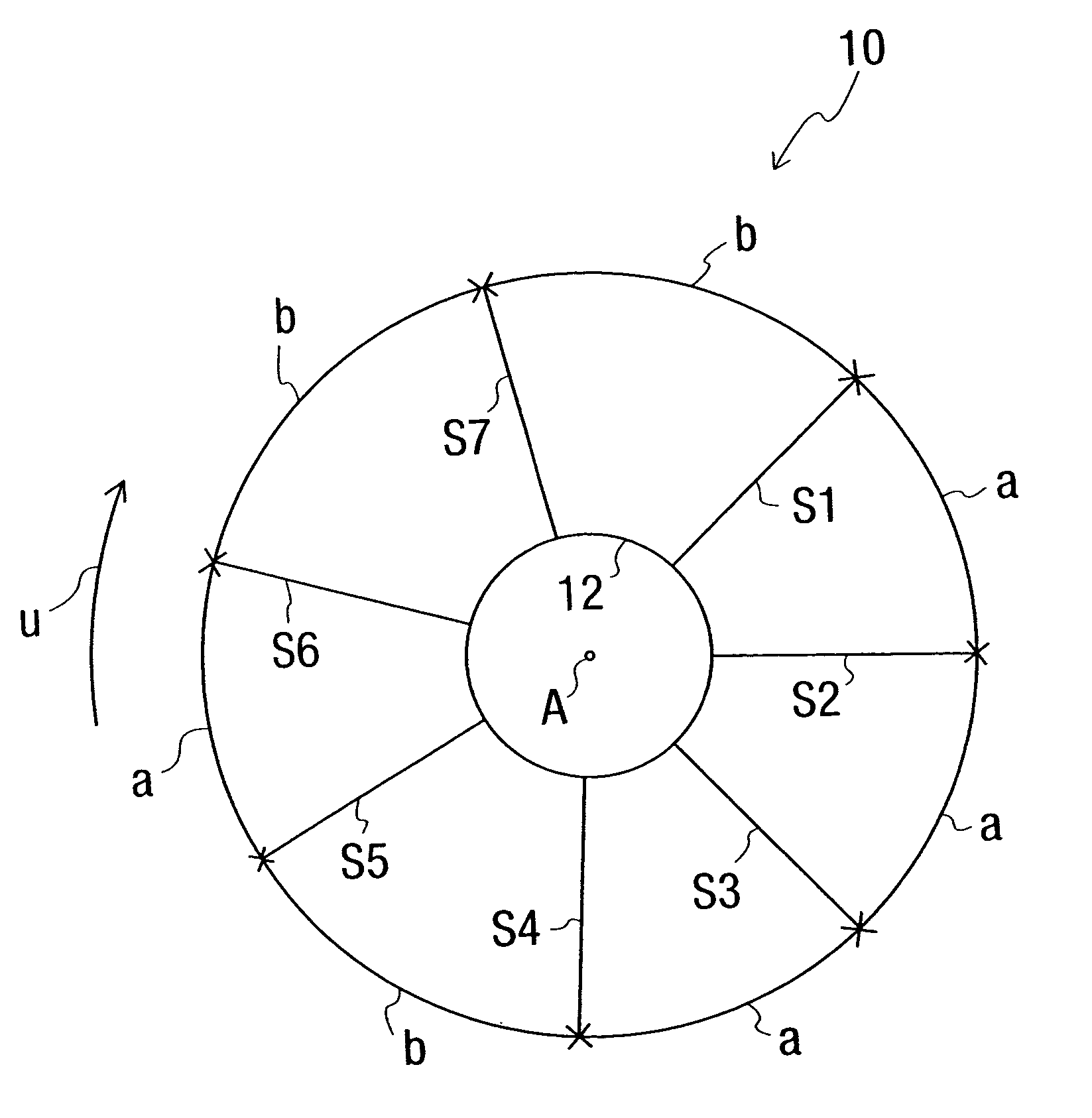
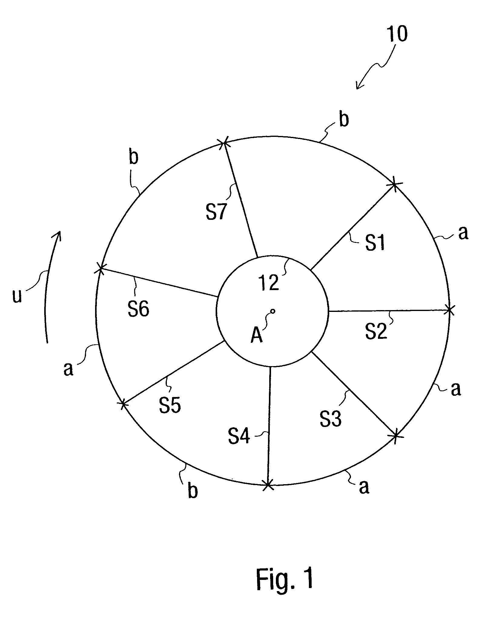
[0027]The design of the conveying member according to the present invention will be described below in reference to a conveying wheel generally designated by 10 in FIG. 1, as it can be used, for example, in a so-called side channel fan. The more specific design of such a side channel fan, which is known per se, will not be explained in greater detail here. However, reference is made in this connection, for example, to DE 39 39 957 A1, which was mentioned in the introduction and shows this general design.

[0028]On a hub 12, which represents equally a shell or a housing of the conveying wheel 10, the conveying wheel 10 according to the present invention has a plurality of blades S1-S7 distributed in such a way that they follow each other in the circumferential direction around an axis of rotation or a center A of this conveying wheel 10. It can be recognized that the blades directly following each other in the circumferential direction U have either a circumferential distance a or a ci...


PUM


Abstract

A conveying member, especially a rotor or stator, for conveying a flowable, preferably gaseous medium, comprises a plurality of blades (S1-S7) arranged following each other with a circumferential distance in a circumferential direction (U) around a central axis (A). Either a first circumferential distance (a) or a second circumferential distance (b) differing from the first circumferential distance (a) is provided between a blade and a respective blade following it in the circumferential direction (U) in a group of blades directly following each other in a circumferential direction (U), which the group comprises at least some of the blades (S1-S7). The first circumferential distance (a) is provided between at least two blades (S1-S7) located directly adjacent to one another, and the second circumferential distance is provided between at least two blades (S1-S7) located directly adjacent to one another.

Description

CROSS REFERENCE TO RELATED APPLICATIONS[0001]This application claims the benefit of priority under 35 U.S.C. § 119 of German patent application DE 10 2004 001 845.6 filed Jan. 13, 2004 the entire contents of which are incorporated herein by reference.FIELD OF THE INVENTION[0002]The present invention pertains to a conveying member, i.e., e.g., a rotor or a stator, by which a fluid or flowable medium, generally a gaseous medium, but, for example, also a liquid medium is conveyed forward.BACKGROUND OF THE INVENTION[0003]A conveying wheel of a half-shell-like design is equipped with a plurality of blades following each other in the circumferential direction around an axis of rotation of a conveying wheel, for example, in so-called side channel fans, as they are used in parking heaters or auxiliary heaters of motor vehicles to convey the combustion air. This conveying wheel rotates with its area carrying the blades above a ring channel at a housing, which ring channel is open on its side...

Claims


Application Information

Patent Timeline
Patent Type & Authority Patents(United States)
IPC IPC(8): F04D29/66F04D29/54F04D29/30F04D29/44
CPCF04D29/544F04D29/666
Inventor KRUGER, JANCASTOR, FRANKNICOLAI, MANFREDROSE, THOMAS
Owner EBERSPAECHER CLIMATE CONTROL SYST GMBH & CO KG
Why Eureka
Try Eureka