Lancer

a technology of lancet and guide member, applied in the field of lancet, can solve the problems of affecting the operation of the plunger, the inability to completely meet the needs of patients and other users, and the inadvertent firing of the lancet, so as to reduce the radial instability of the guide member

Inactive Publication Date: 2010-01-26
BECTON DICKINSON & CO
View PDF28 Cites 26 Cited by
  • Summary
  • Abstract
  • Description
  • Claims
  • Application Information

AI Technical Summary

Benefits of technology

[0018]The present invention is drawn to an improved lancer having features that improve the safety of the device and increase the comfort of the patient. The lancer can include a triggering mechanism that will be actuated when a user deliberately applies the required force to fire the lancet. A swift release and retraction of the lancet provides improved operation of the lancer. The lancer also optionally has an adjustable tip portion that permits a user to select a desired depth of stylet penetration from a number of depth-penetration choices. This feature facilitates an adequate, reproducible lancing for the user or patient. The lancer may also optionally include an ejection mechanism that releases a used lancet without the user or patient touching the used lancet. The lancer optionally includes a vibration-reducing and dampening mechanism to increase patient comfort. These features provide an improvement over conventional lancer devices.
[0022]Yet another embodiment is directed to an apparatus for propelling a lancet. This apparatus includes a body assembly, which has a proximal portion, a distal portion, and an orifice. A guide member is disposed in the body assembly, for guiding the lancet. An ejection mechanism is disposed in the body assembly, for preventing retraction of a lancet, when the guide member is rearwardly moved beyond a latching position, thereby detaching the lancet from the guide member following rearward positioning of the guide member. This rearward positioning of the guide member is facilitated by detachment of the nose portion.
[0024]Yet still another embodiment is directed to an apparatus for propelling a lancet. A body assembly has a proximal portion, a distal portion, and an orifice disposed at the distal portion. A guide member is disposed in the body section, for guiding the lancet. A latch, for actuating the guide member, is disposed in the body assembly. A means for dampening vibration is disposed on the guide member for reducing vibration of the guide member.
[0033]Yet still another embodiment is directed to a lancer device having a retention mechanism for preventing the device from inadvertently becoming armed when a user is attempting to load or unload a lancet. This device includes a guide member, disposed in a body assembly, for guiding the propelled lancet. A latch is disposed in the housing assembly and has at least one notch for engaging the guide member when the guide member is retracted. Actuation of the latch causes the guide member to disengage from the notch and propel the lancet toward the orifice at the distal portion of the body assembly. A retention mechanism, disposed in parallel with the longitudinal axis of the apparatus abuts a portion of the lancet and thereby prevents axial motion of the lancet. Thus, after firing, a portion of the latch prevents retraction of the guide member in the proximal direction.
[0034]Yet still another embodiment is directed to an apparatus for propelling a lancet. This apparatus has a body assembly, having a proximal portion, a distal portion, and an orifice disposed at the distal portion. A guide member is disposed in the body assembly, for guiding the propelled lancet. The apparatus also has means for reducing radial instability of the guide member while the guide member is propelling the lancet.

Problems solved by technology

This lancer, however, does not completely meet the needs of patients and other users, such as medical personnel who employ the lancers to obtain samples from patients, for reasons described below.
This pawl-like or detent-based trigger, however, can be actuated with relatively little force, which may result in an inadvertent firing of the lancet and the accidental piercing of the patient's or user's skin.
That bias force, however, is not in the same direction of the spring force on the plunger, and may adversely affect the operation of the plunger by causing it to deviate from its axial path of motion.
This in turn can reduce patient comfort upon penetration of the stylet.
Generally, as the stylet penetration depth increases, the amount of blood increases, as well as the patient discomfort.
If the penetration depth is set by the lancer design to be too shallow for the specific patient, the stylet may not adequately pierce the patient's skin, and repeated lancing attempts or smaller gauge (larger diameter) stylets may be required to extract the required amount of blood, which in turn wastes time and / or lancets, and in any event increases patient discomfort.
On the other hand, if the lancer is designed to cause the stylet to penetrate too deeply for a specific patient, unnecessary discomfort will be incurred by that patient, as well as a longer recovery time.
However, to achieve this precise plunger control, complicated drive mechanisms involving many low tolerance and expensive components are required, as well as time-consuming and labor-intensive assembly.
However, this device requires the manufacture and assembly of three discrete elements.
Moreover, because the bottom cover element moves to achieve a variation in depth, the overall length of the lancer will vary depending on the adjustment setting, inhibiting easy storage and use of the lancer.
When the outer sleeve is rotated, the cam forces the outer sleeve to move away from the lancer, thus increasing the distance between the lancet stop and the bottom of the outer sleeve, which in turn decreases the depth penetration.
This assembly, however, suffers from the same problems as the previously described one.
In another aspect of conventional lancer operation, after the lancet has been used to draw blood from a patient it becomes contaminated with blood and, thus, poses a potential health hazard to anyone else who might be stuck by its stylet.
Unfortunately, if the operator removes a finger from the control member prior to complete separation, an accidental lancet ejection can result.
This solution is less than optimal since there is still a possibility of accidental ejection.
Other known ejection mechanisms tend to be cumbersome and require complicated manipulations, which are difficult for blind or disabled diabetics to accomplish, and increase the likelihood of accidental needle stick injury.
In another aspect of conventional lancers, the spring-loaded plunger / lancet assembly may produce vibrations upon it being fired.
These vibrations may thus reduce the optimum propulsion of the lancet and reduce the comfort of the patient, because even small vibrations can be sensed by the patient upon lancing of the skin.

Method used


Image

  • Lancer
  • Lancer
  • Lancer

Examples


first embodiment

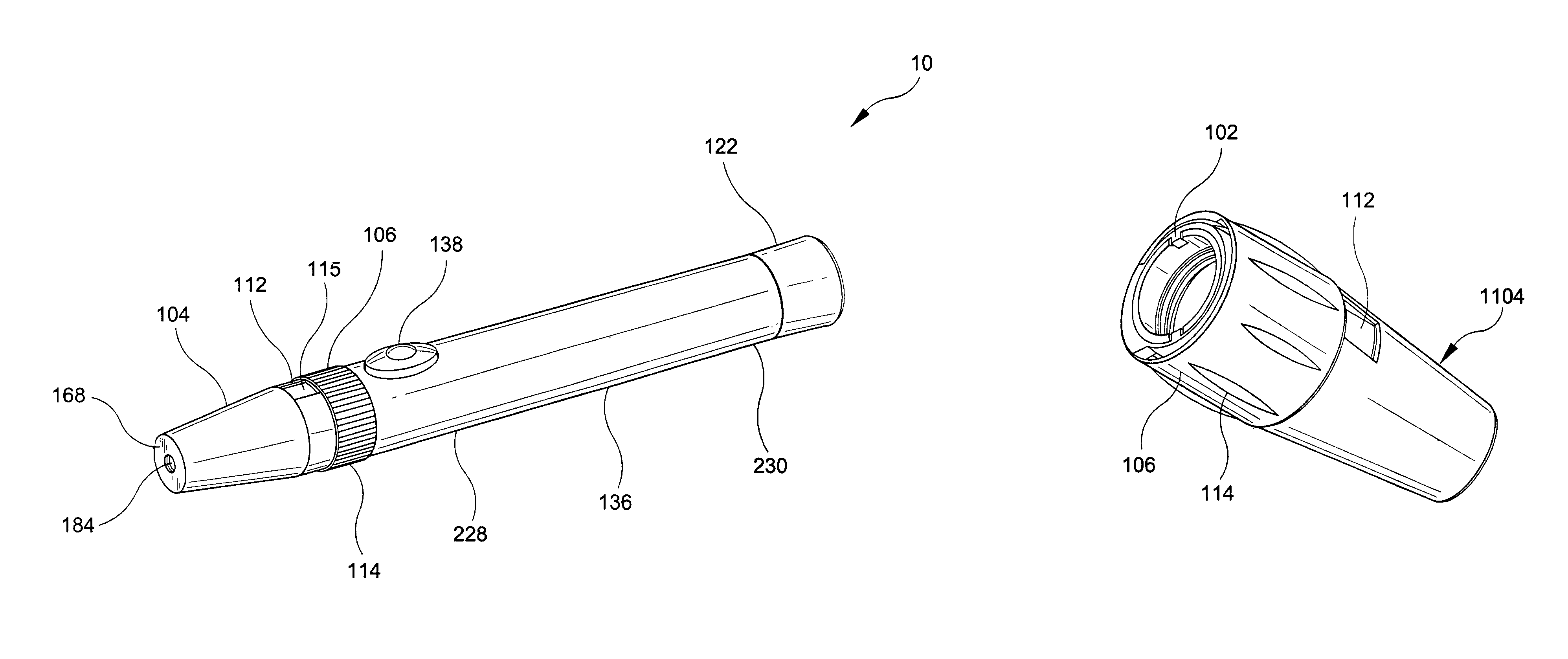
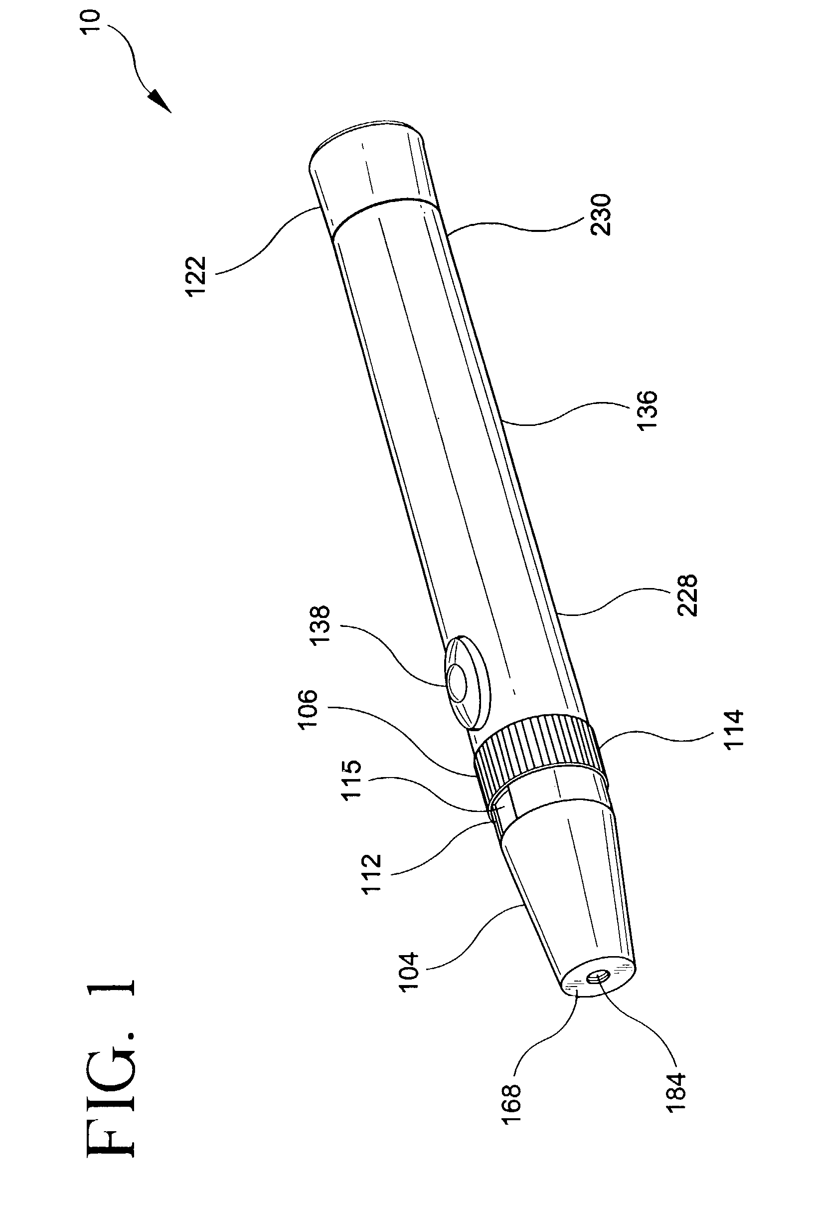
[0104]FIGS. 5A and 5B show the adjustment assembly 108. FIG. 5A shows the adjustment assembly 108 suitably attaches to the body assembly 136 of a lancer device. The adjustment assembly 108 has two portions. These are an outer member and an inner member. The outer member is shown as nose portion 104 and adjustment member 106. FIG. 5B shows outer member as element 1106, which is suitably prevented from translation with respect to tip thread member 116.

[0105]As shown in FIG. 5A, the outer member 104, 106 has a distal portion toward orifice 184 and a proximal portion toward body assembly 136. Surface 168(a) is an exterior surface and surface 168(b) is an interior surface of outer member 104, 106.

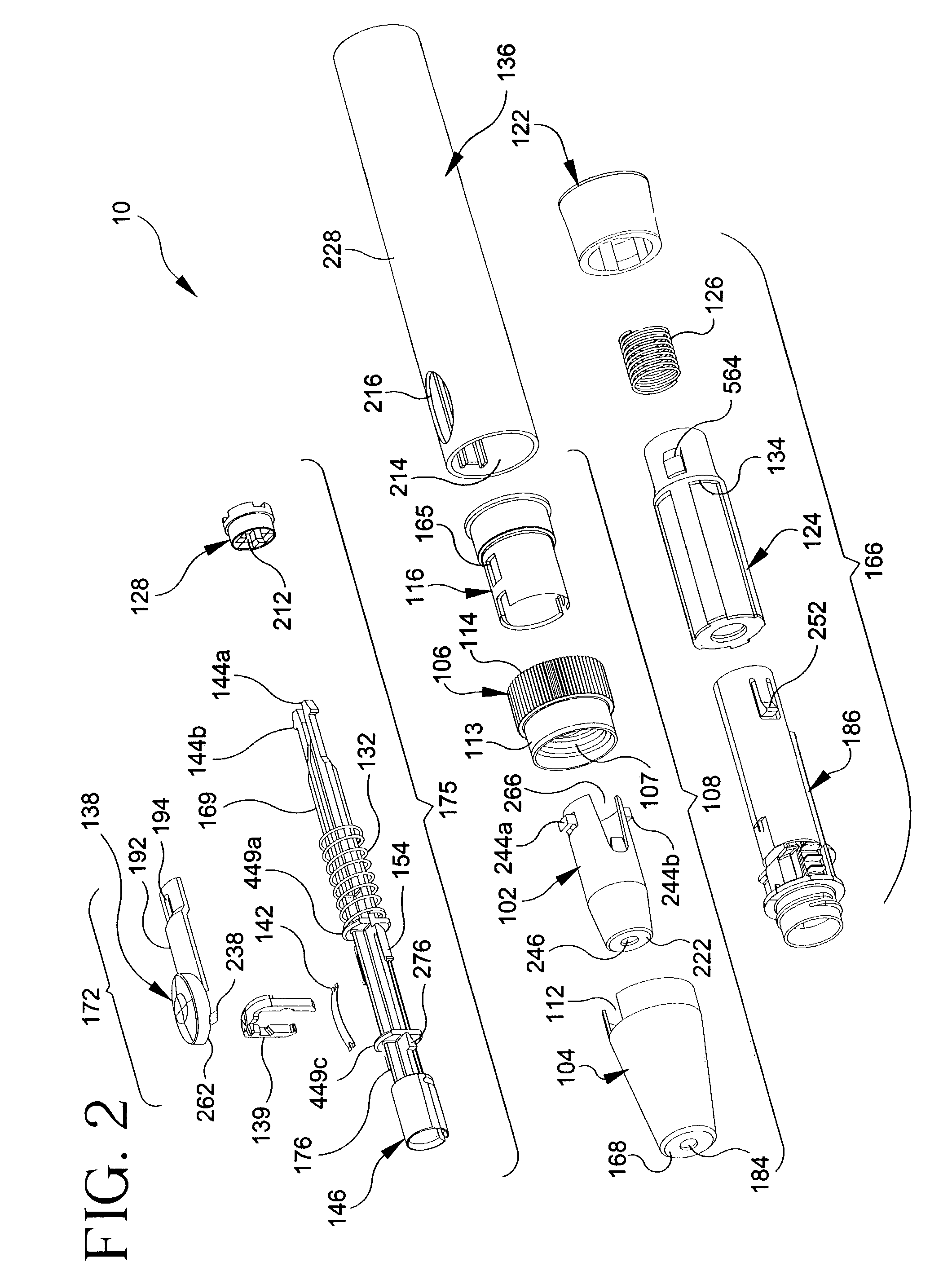
[0106]Inner member, also referred to as lancet stop herein, 102 has exterior distal surface 222(a) and interior distal surface 222(b). Inner member 102 also has orifice 246 and protrusions, or posts, 244(a) and (b). These protrusions 244(a) and 244(b) interact with slots 165(a) and 165(b), respe...

third embodiment

[0109]FIGS. 7 and 8 show the adjustment mechanism. Adjustment mechanism 308 is suitably attached to a lancer device. Member 328 is suitably a part of the adjustment mechanism or, alternatively, the distal portion of the body assembly to which the adjustment mechanism is affixed. In this embodiment, the user pulls the outer member 304 distally and rotates it, moving the outer member 304 from the stopping face 332. (A plurality of stopping faces are designated generally by numeral 332.) Operation of this embodiment involves a user pulling nose 304 to release protrusion 349 from slot one of the slots, shown generally as numeral 331, therefore, allowing relative rotation of 304 and 328. While the relative rotation is occurring, no translation between surface 322 and surface 368 occurs. While the outer member 304 is pulled away from the body assembly 328, the stopping face 332 is moved distally so that the protrusion 349 is removed from the associated slot 331 and is able to float above ...

fourth embodiment

[0115]FIGS. 10A and 10B show perspective and cross-sectional exploded views, respectively, of the adjustment assembly 408. This embodiment utilizes a collar member 335 having interior camming surface 333 to attach inner member 302 and outer member 304 to body assembly 328.

[0116]As shown in FIGS. 10A and 10B, the interior surface of outer member 304 has a plurality of slots 331(a) . . . (d) (where d is any number compatible with the dimensions of the outer member). Protrusion 349, disposed on an exterior surface of inner member 302, suitably interfaces with a selected slot 331(a) . . . (d) in a substantially mating relationship. A user or patient selects a desired penetration depth by pulling and rotating the outer member 304 such that protrusion 349 abuts an interior surface of a slot 331(a) . . . (d). The inner member 302 is held in position; and surface 322(b) is fixed relative to surface 368(a).

[0117]Camming surface 341 is disposed in body assembly 328 for attaching assembly 328 ...


PUM


Abstract

A lancer device that enables a user to draw blood from a patient and discard the used lancet without touching it. The device also has an adjustable tip for selecting the depth of stylet penetration into the patient and a triggering mechanism that utilizes a yoke latch and a leaf spring to discharge the lancet. The lancer also has a dampening feature to reduce vibrations when the lancet is moving.

Description

[0001]This is a continuation of U.S. application Ser. No. 09 / 366,149, filed Aug. 3 1999, now U.S. Pat. No. 6,558,402.BACKGROUND OF THE INVENTION[0002]1. Field of the Invention[0003]The present invention relates to a lancer for withdrawing a sample of blood from a patient via a lancet. More particularly, the invention is drawn to a lancer having a latch triggering mechanism for actuating the device. The lancer optionally has an adjustable tip for setting the depth of penetration of the lancet into the patient's skin by moving a lancet stop back and forth. The lancer may further include an ejection mechanism for automatically causing the release of the lancet from the lancer without the need to handle the lancet. Moreover, the lancer may include a dampening mechanism, such as a wisp, for reducing vibrations in the lancet, thus increasing patient comfort. The lancet may further include a centering mechanism to decrease undesired motions of the lancet perpendicular to the axial directio...

Claims


Application Information

Patent Timeline
Patent Type & Authority Patents(United States)
IPC IPC(8): A61B17/14A61B5/151A61B5/15A61M1/02
CPCA61B5/1411A61B5/15186A61B5/150022A61B5/150106A61B5/15019A61B5/150503A61B5/150412A61B5/15113A61B5/15117A61B5/1519A61B5/15194A61B5/150587A61B5/150717
Inventor CHELAK, TODD M.GABEL, JONATHAN B.WEST, ROBERT E.ALLEN, WILLIAM J.BACHMAN, ALANREED, SCOTT W.ADAMS, RAY
Owner BECTON DICKINSON & CO
Why Eureka
Try Eureka