Method and apparatus for detecting an object through the use of multiple sensors

a technology of multiple sensors and objects, applied in electrical apparatus, instruments, surveying and navigation, etc., can solve the problems of inability to differentiate, inability to compute the computing time effort in the evaluation unit for the required coordinate transformation, and inability to free define the protected zone inside the monitored space. , to achieve the effect of reducing the computing effort in the processing of pictures, reducing the load of the evaluation unit, and increasing the process speed

Active Publication Date: 2010-01-26
SICK AG
View PDF5 Cites 24 Cited by
  • Summary
  • Abstract
  • Description
  • Claims
  • Application Information

AI Technical Summary

Benefits of technology

[0012]A further advantage of the invention lies in the fact that the generation of the single images takes place in a uniform coordinate system for all sensors in that either all sensors operate in the same coordinate system from the start or the required transformation into the uniform coordinate system is carried out by each sensor itself. The load of the evaluation unit can thereby be substantially reduced so that the resulting process speed can be increased. The flagging as a safe or unsafe zone at the level of the sensors also effects a corresponding relief of the evaluation unit.
[0013]It is generally possible for only an explicit flagging of the safe coordinate points to take place, whereas the remaining coordinate points are not explicitly flagged as unsafe, but only implicitly by their “non-flagging”.
[0014]In accordance with a preferred embodiment of the invention, the resulting total image is superimposed with a danger zone fixed by the evaluation unit and in particular changing dynamically and a safety-relevant function is triggered when at least a pre-determined number of coordinate points flagged as unsafe is determined inside the danger zone. In accordance with this embodiment, an evaluation of the object recognition is thus possible with respect to a pre-determined danger zone such as is defined, for example, in safety engineering for hazardous machinery. Depending on the application and in particular on the resolution used, the safety-relevant function can already be triggered on the determination of a single unsafe coordinate point or only with a plurality of such points inside the danger zone.
[0015]The danger zone can, for example, be the effective area of a machine, in particular of a robot, while the object to be sensed is formed by a person who is located inside the monitored zone and has to be protected against a dangerous contact with the robot. With the invention, a safety-relevant function, e.g. a switching off of the machine, is only triggered when the sensed object actually intrudes into the danger zone of the machine. If an object is sensed inside the monitored zone by a sensor such that the “shadow” of the object which can be seen into by the sensor comes to lie between the object and the machine, in accordance with the invention the safety-relevant function is not triggered as long as at least one of the sensors can seen into this shadow zone and thus classifies the coordinate points of this zone as “safe”.
[0016]The single images of the different sensors preferably each have the same resolution (discretization). The superimposition of the pictures in the evaluation unit can thereby be accelerated since a further conversion inside the evaluation unit is not necessary. The computing effort in the processing of the pictures can thus be reduced so that the size of the required danger zone can be minimized since a shorter reaction time is achieved on the triggering of the safety-relevant function. Ultimately, an enlarging of the effective circle of the machine can thereby be achieved.
[0017]Advantageously, the common monitored zone is defined for each sensor in an initialization phase and its own position is fixed with respect to the monitored zone. A uniform reference system of all sensors and a uniform format of the sensor data which should be sent to the evaluation unit are guaranteed by this initialization phase. It is in particular important to fix the respective position of each sensor with respect to the monitored zone since the sensor data are no longer transmitted to the evaluation unit in a coordinate system centered on the respective sensor, but the data transmitted to the evaluation unit should rather be transmitted in a uniform coordinate system for all sensors.

Problems solved by technology

It is problematic in this process that a breach of the protected zone reported by a sensor does not necessarily mean that the sensed object is also breaching the danger zone of the machine.
Since the sensor cannot see into the zone disposed between the object and the machine, it is not possible to differentiate whether the part of the object remote from the sensor reaches up to and into the danger zone of the machine or not.
It is furthermore a disadvantage that a definition always has to be made up to the sensor due to the described cast shadow of the protected zone of the sensors so that a free definition of the protected zone inside the monitored space is not possible.
Finally, the computing time effort in the evaluation unit for the required coordinate transformation is relatively high so that high computing power is in particular required for a time-critical application when a plurality of sensors are used.

Method used


Image

  • Method and apparatus for detecting an object through the use of multiple sensors
  • Method and apparatus for detecting an object through the use of multiple sensors
  • Method and apparatus for detecting an object through the use of multiple sensors

Examples


Embodiment Construction

[0031]The following description of the preferred embodiment(s) is merely exemplary in nature and is in no way intended to limit the invention, its application, or uses.

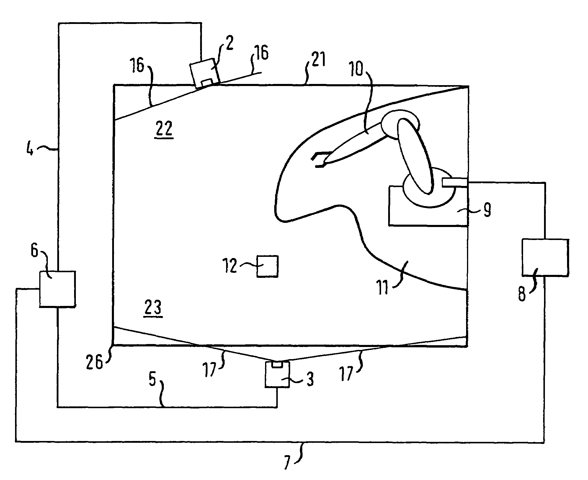
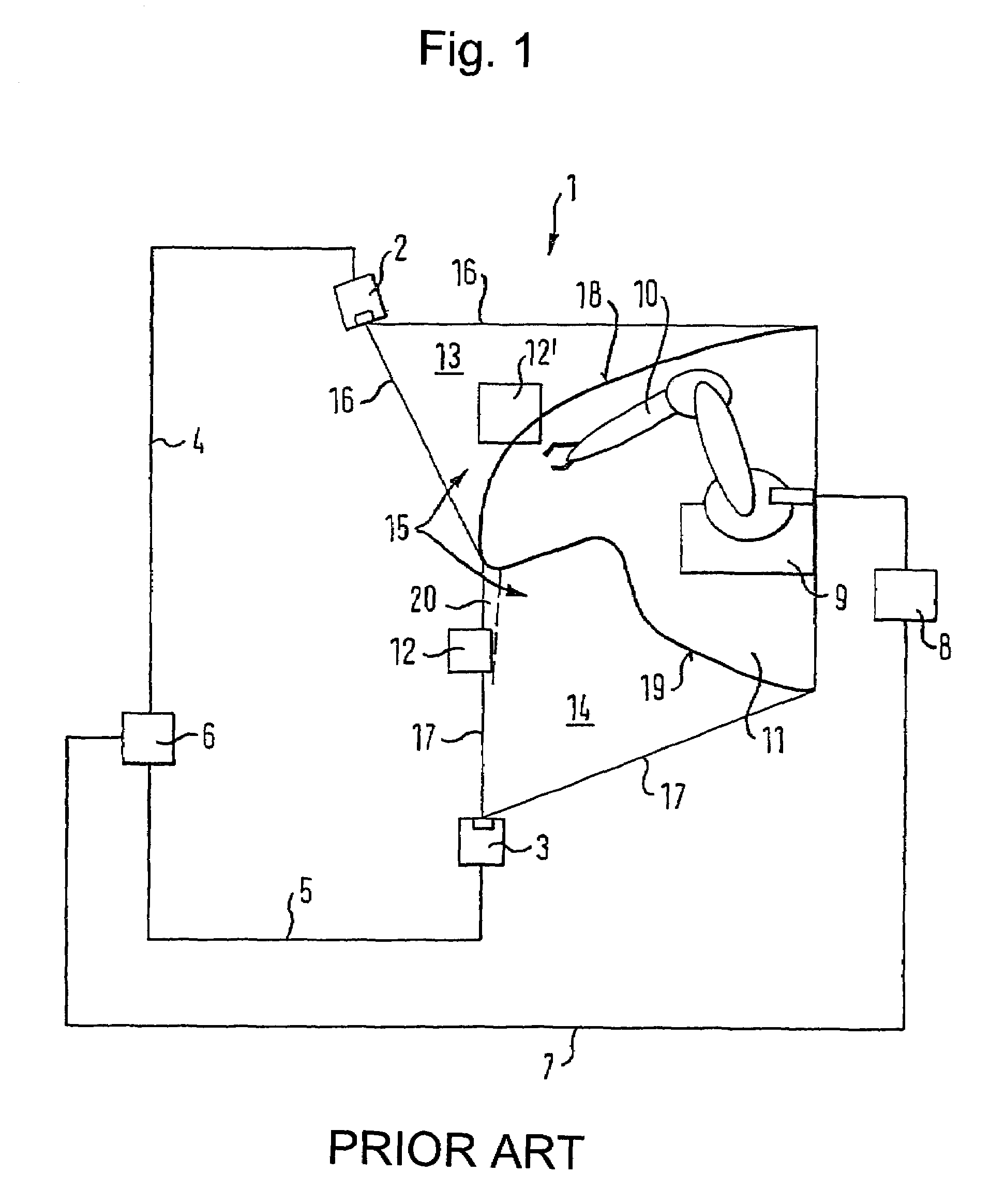
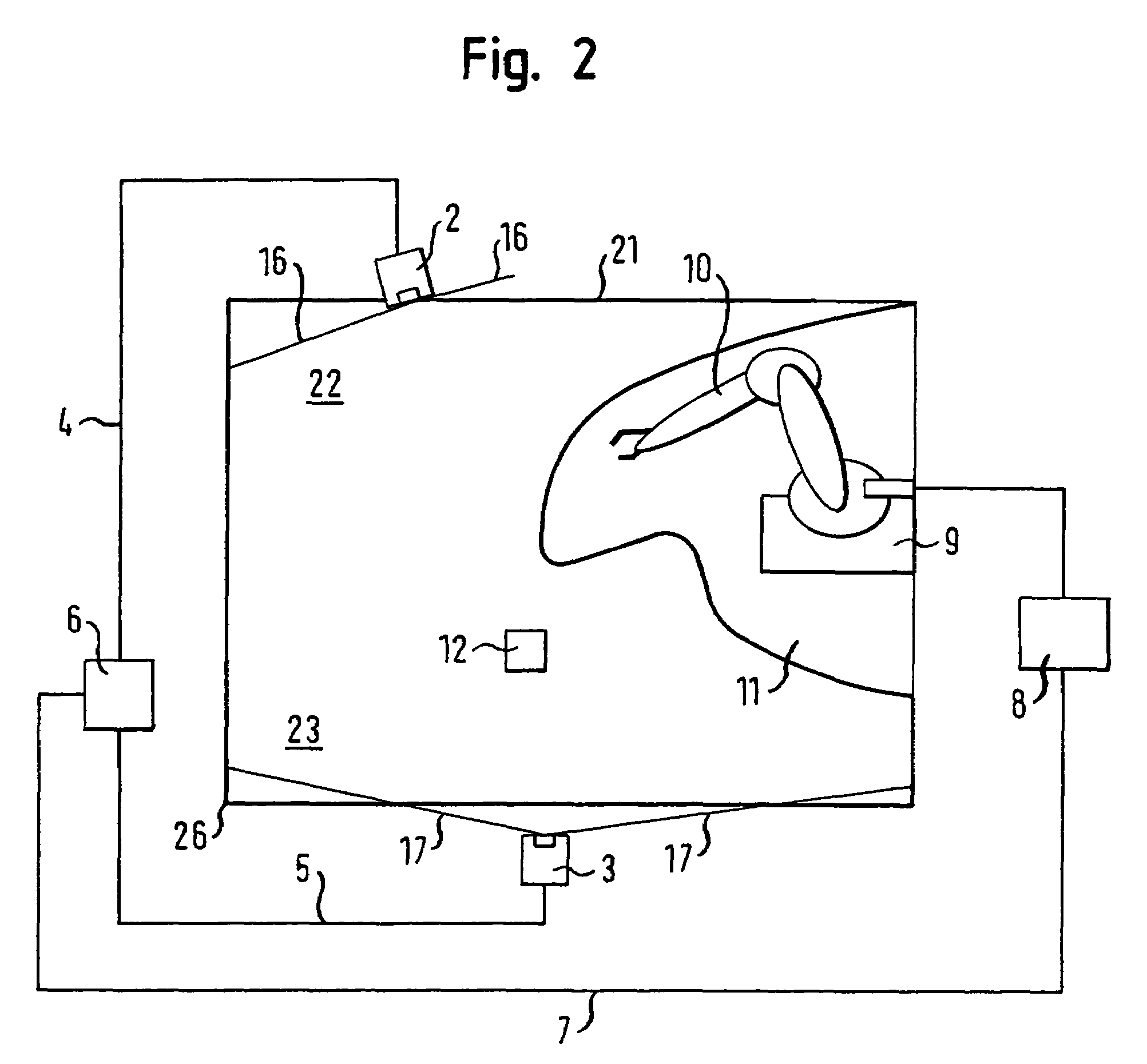
[0032]FIG. 1 shows a monitoring apparatus 1 in accordance with the prior art with area scanners 2, 3 designed as laser scanners which are each connected to an evaluation unit 6 by leads 4, 5. The evaluation unit 6 is connected via a further lead 7 to a machine control 8 of a machine 9 designed as a robot and including a movable robot arm 10. A safety-relevant function of the machine control 8 can be triggered, for example the machine 9 switched off, by the evaluation unit 6 via the lead 7.

[0033]A danger zone 11 which is monitored by the sensors 2, 3 is defined by the movement of the robot arm 10. Objects intruding into the danger zone 11 can be put at risk by the movements of the robot arm 10 so that an intrusion of this kind must, for example, result in a switching off of the machine 9 by the evaluation unit 6. In FI...


PUM


Abstract

A method for detecting an object inside a monitored zone includes monitoring at least a part of a monitored zone. Sensors generate respective single digital images of the total monitored zone, with the single images of all sensors being generated in a uniform coordinate system. Coordinate points of the single images are flagged as “safe” by each sensor if they are free of the object, with all other coordinate points being flagged as “unsafe”. The single images are each transmitted to an evaluation unit and are superimposed to form a resulting total image. The coordinate points of the total image, which are flagged as “safe”, correspond to those flagged as safe in at least one of the single images. All other coordinate points of the total image are flagged as unsafe. The coordinate points flagged as unsafe in the total image are used for the determination of the object coordinates.

Description

CROSS-REFERENCE TO RELATED APPLICATIONS[0001]This application claims the benefit of German Patent Application No. DE 10 2004 043 515.4, filed on Sep. 8, 2004. The disclosure of the above application is incorporated herein by reference.FIELD AND BACKGROUND OF THE INVENTION[0002]The present invention relates to a method for detecting an object inside a monitored zone, in which at least two sensors respectively monitor at least a part of the monitored zone. The invention is furthermore directed to an apparatus for use in a method of this type.[0003]Methods of this type are in particular used in safety engineering. A check is, for example, made continuously whether an object, in particular a person, sensed inside the monitored zone, intrudes into the danger zone of a machine, for example a robot, working inside the monitored zone. If an intrusion of this type is detected, the machine can be switched off or another suitable safety function can be triggered.[0004]When laser scanners desig...

Claims


Application Information

Patent Timeline
Patent Type & Authority Patents(United States)
IPC IPC(8): G01C21/02G06M7/00F16P3/14
CPCF16P3/147F16P3/144
Inventor HABERER, MANFREDROTHENBERGER, BERNDNATZKOWSKI, CARSTEN
Owner SICK AG
Why Eureka
Try Eureka