
Optical device

a technology of optical devices and flashing devices, applied in the field of optical devices, can solve the problems of limited available space, unsuitable for such use, and the flashing of zoom flashes described above with a focusing device, and achieve the effect of less sensitive to mechanical shock and precise adjustmen

Inactive Publication Date: 2010-01-26
SONY CORP
View PDF29 Cites 11 Cited by
  • Summary
  • Abstract
  • Description
  • Claims
  • Application Information

AI Technical Summary

Benefits of technology

The invention is an optical device that uses a light emitting element to take photos of objects. The device has multiple light emitting zones that can be controlled to emit light with different intensity levels. This allows for flexible and precise lighting, and can be used in mobile devices or as an independent accessory for imaging devices. The device can also analyze the image and adjust the light emitting zones accordingly. Additionally, the device can have a variable focal length, which can be used to control the zoom of the image. The device is less sensitive to mechanical shock and has no moveable parts that require precise adjustment.

Problems solved by technology

In e.g. mobile communication devices, such as mobile telephones, small cameras are used, where the available space is limited.
A traditional zoom flash as described above with a focusing device that is moveable relative to the light source is not suitable for such use due to its space requirements.
Also this device is quite large and thus less suitable for small mobile devices.

Method used


Image

  • Optical device
  • Optical device
  • Optical device

Examples


Embodiment Construction

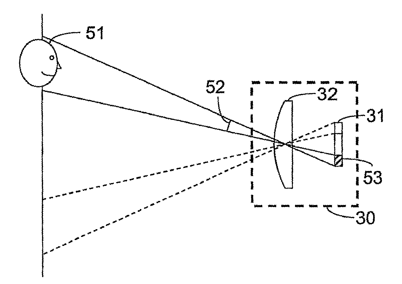
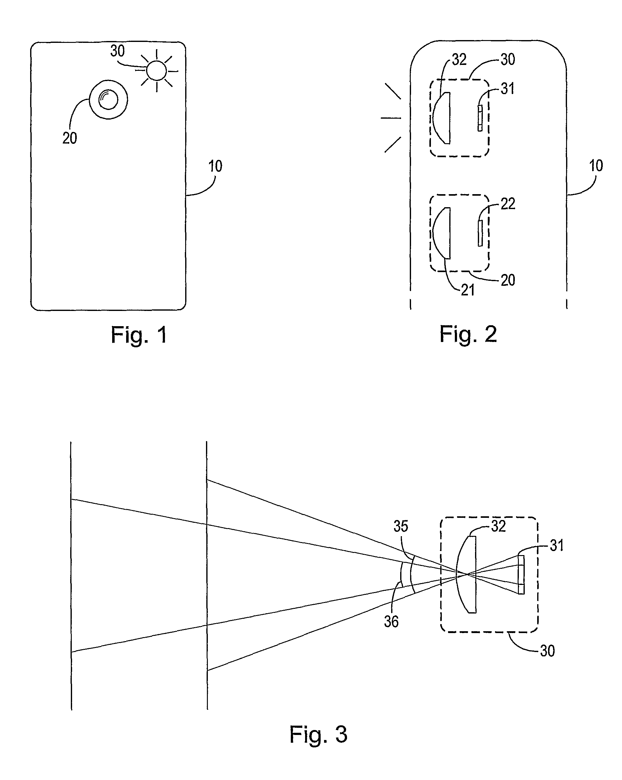
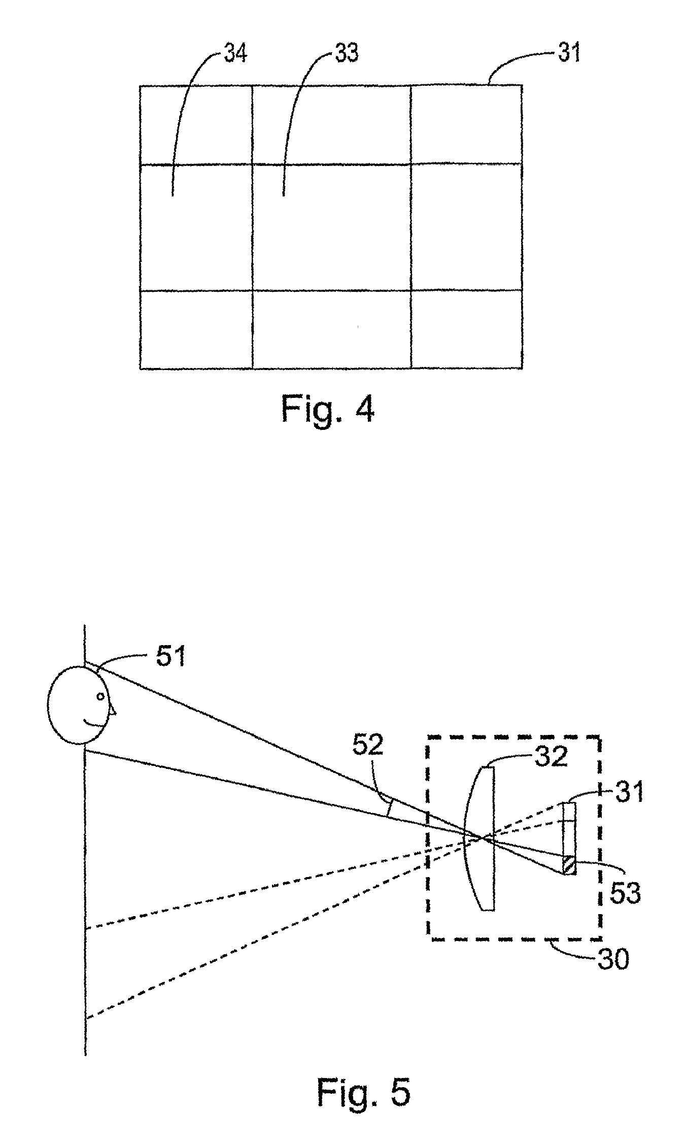
[0033]In FIGS. 1 and 2 is shown the contour of a mobile telephone 10 with a camera 20 or other means for taking photographic images and an illumination device 30 that can be controlled to emit light for illuminating an object to be photographed by the camera 20. The mobile telephone 10 has means for wireless voice communication, which are not shown.

[0034]The camera 20 comprises an imaging lens 21 arranged in an imaging relationship with a light sensitive element 22 so as to project light from the object onto the light sensitive element to form an image of the object thereon. In the illustrated example the light sensitive element 22 is e.g. a charge-coupled device (CCD), and the images taken are digital images. Alternatively, the light sensitive element comprises a film with a light sensitive emulsion on a carrier.

[0035]The digital camera 20 is capable of zooming, i.e. varying the opening angle, i.e. the spatial angle within which objects are imaged on the light sensitive element 22....


PUM


Abstract

An optical device for use with an imaging device for taking photographic images of an object includes a light emitting element capable of emitting light, and a lens arranged so as to direct light from the light emitting element to illuminate the object. The light emitting element may include at least two light emitting zones arranged so that light from the light emitting zones can be directed from the lens in respective corresponding spatial angles, and that the light emitting zones can be individually and selectively controlled to emit a controllable intensity of light.

Description

CROSS-REFERENCE TO RELATED APPLICATIONS[0001]This application is a 35 U.S.C. § 371 national phase application of PCT Application No. PCT / EP2006 / 001100, filed on Feb. 3, 2006, which claims priority from European Patent Application Serial No. 05388009.2 filed on Feb. 3, 2005, and which claims the benefit under 35 USC § 119(e) of U.S. Provisional Application Ser. No. 60 / 652,682 filed on Feb. 14, 2005, the disclosures of which are incorporated by reference herein in their entireties. The above-referenced PCT International Application was published in the English language as International Publication No. WO 2006 / 082112 on Aug. 10, 2006.TECHNICAL FIELD OF THE INVENTION[0002]The invention relates to optical devices for use with an imaging device such as a camera for taking photographic images of an object and for illuminating the object when taking the image.DESCRIPTION OF RELATED ART[0003]Traditional analogue and digital cameras use a flash with a discharge tube and a lens, a concave mirr...

Claims


Application Information

Patent Timeline
Patent Type & Authority Patents(United States)
IPC IPC(8): G03B15/02H04M1/02H04N5/225
CPCG03B15/02H04N5/2256H04N5/23296H04M1/22Y10S362/80H04M2250/52H04N23/56H04N23/69
Inventor WERNERSSON, MATS
Owner SONY CORP
Learn More