Systems and methods of beamforming in radio frequency identification applications

a beamforming and radio frequency identification technology, applied in the field of systems and methods of beamforming in radio frequency identification applications, can solve the problems of limited maximum read range of rfid readers, time-consuming manual configuration and/or tuning, and bulky coaxial cables. achieve the effect of facilitating deployment of rfid applications and enhancing read range and reliability

Inactive Publication Date: 2010-01-26
WIRAMA CORP +1
View PDF29 Cites 268 Cited by
  • Summary
  • Abstract
  • Description
  • Claims
  • Application Information

AI Technical Summary

Benefits of technology

[0008]The present invention includes a beamforming system for enhancing read range and reliability in RFID applications, and facilitates deployment of RFID applications by non-experts. A distributed architecture uses techniques for antenna beamforming and a feedback control loop to direct radio frequency (RF) energy onto a specific region, referred to as an interrogation zone, which includes a calibration node where one or more RFID tags may be located.

Problems solved by technology

The maximum read range of an RFID reader is typically limited by the power needed to energize the tag and to generate the backscatter response.
However, there are a number of problems with the conventional approach.
For example, coaxial cable is bulky and expensive.
This manual configuration and / or tuning is time consuming and requires technicians skilled in radio frequency technology.
Moreover, the configuration and / or tuning may no longer function when there are changes in the radio frequency environment or when the RFID tags are in motion.

Method used


Image

  • Systems and methods of beamforming in radio frequency identification applications
  • Systems and methods of beamforming in radio frequency identification applications
  • Systems and methods of beamforming in radio frequency identification applications

Examples


Embodiment Construction

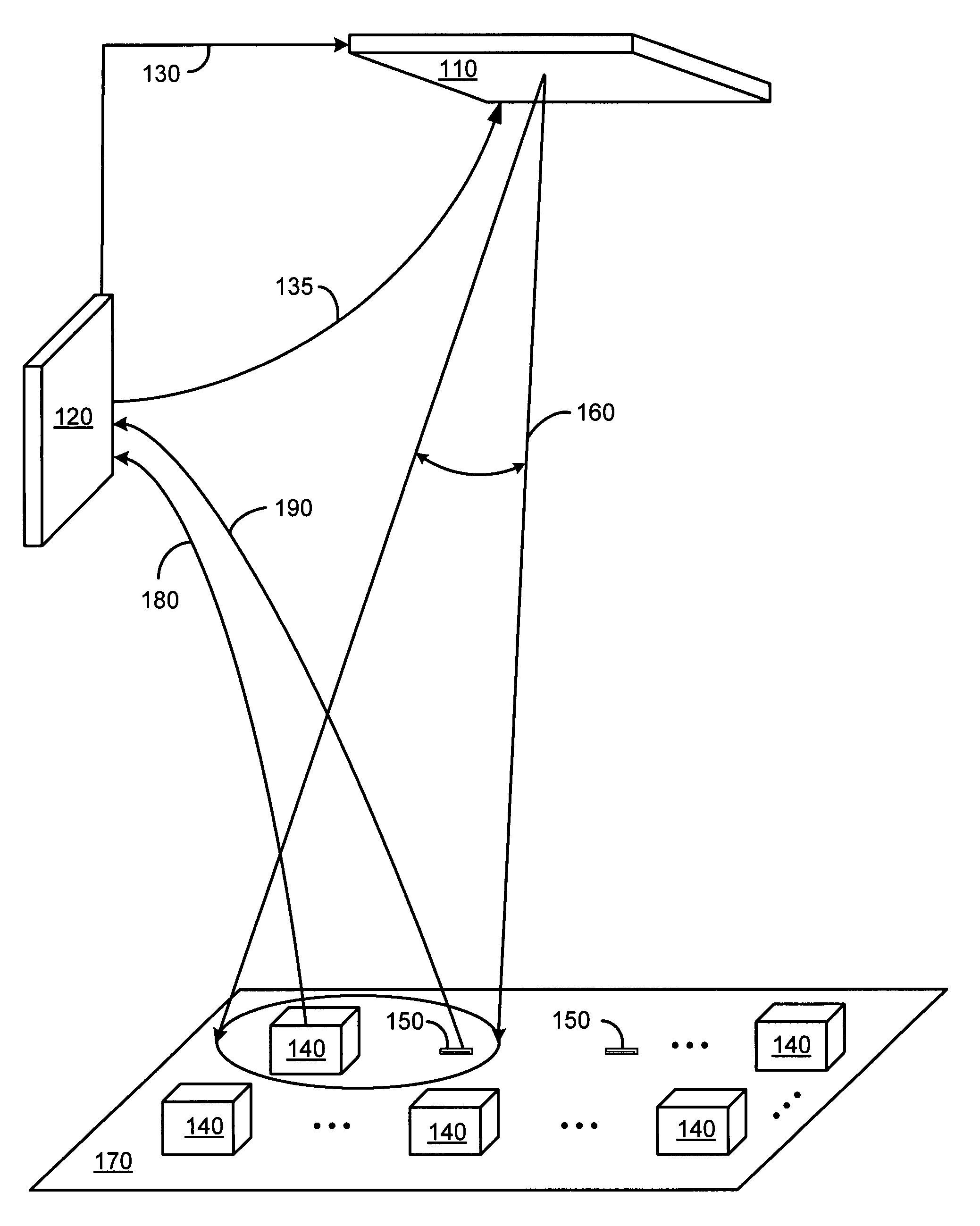
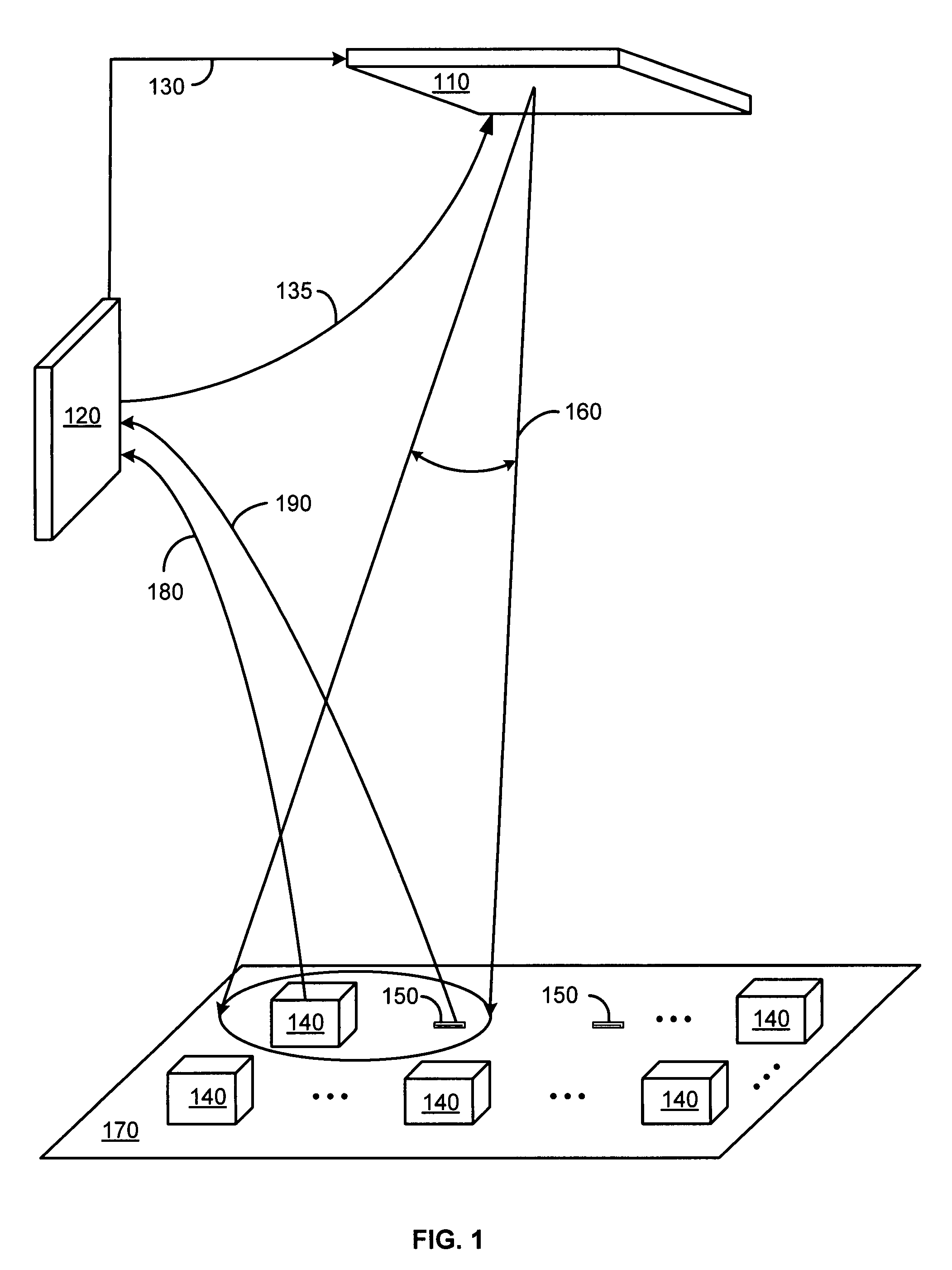
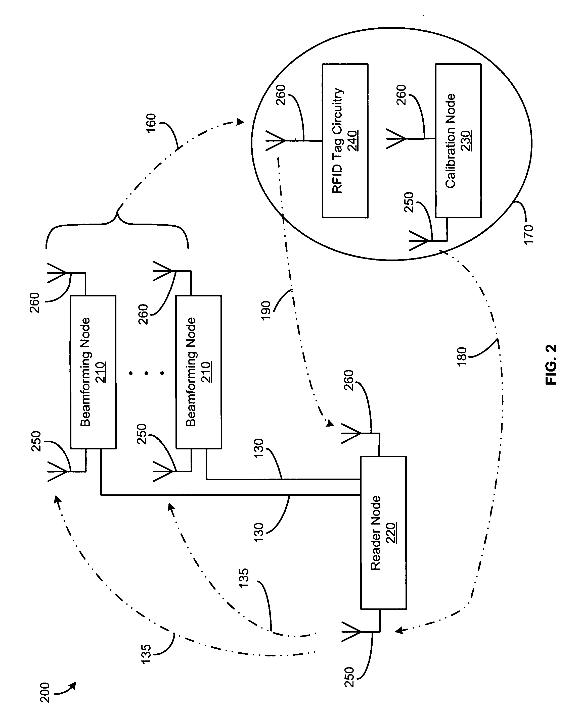
[0026]The present invention includes systems and methods for beamforming in radio frequency identification applications. A distributed architecture uses techniques for antenna beamforming and a feedback control loop to direct radio frequency (RF) energy onto a specific region including a calibration node, referred to as an interrogation zone, where one or more RFID tags may be located.

[0027]The distributed architecture of the beamforming system is resistant to fading and shadowing effects, providing accurate RFID reader operation even in environments with multi-path reflections or environmental changes, such as people moving around, changes in the location of equipment, etc. By connecting the beamforming nodes to the RFID reader node using a wireless coupling, the need for coaxial cable is eliminated. The distributed architecture also enables the use of low-cost, low-data rate wires for communication between the reader node and the beamforming nodes. Furthermore, the architecture of...


PUM


Abstract

Systems and methods for beamforming in radio frequency identification (RFID) applications are disclosed. A beamforming system uses a distributed architecture and techniques for antenna beamforming using a feedback control loop to direct radio frequency (RF) energy onto a specific region, referred to as an interrogation zone, which includes a calibration node where one or more RFID tags may be located. The distributed architecture of the beamforming system is resistant to fading and shadowing effects, providing accurate RFID reader operation even in environments with multi-path reflections or environmental changes, such as people moving around or changes in the location of equipment.

Description

CROSS-REFERENCE TO RELATED APPLICATIONS[0001]This application claims the benefit of U.S. Provisional Application Ser. No. 60 / 765,331 titled “Methods and architectures for increasing range and reliability in RFID systems,” filed Feb. 4, 2006, which is hereby incorporated by reference.BACKGROUND OF THE INVENTION[0002]1. Field of the Invention[0003]The present invention relates generally to radio frequency identification (RFID) applications, and more particularly to systems and methods of beamforming in RFID applications.[0004]2. Description of Related Art[0005]Many radio frequency identification systems use batteryless tags that can be identified by a reader through radio frequency communication to label items. In these systems, an RFID reader (comprising a radio frequency transmitter and receiver) energizes the tag and then receives data from the tag. Conventional readers for passive RFID systems typically operate by the RFID reader first sending an unmodulated radio frequency (RF) s...

Claims


Application Information

Patent Timeline
Patent Type & Authority Patents(United States)
IPC IPC(8): G08B13/14
CPCG06K7/10346
Inventor MADHOW, UPAMANYUWILD, BEN J.RAMCHANDRAN, KANNAN
Owner WIRAMA CORP
Why Eureka
Try Eureka