Method and apparatus for dissipating heat from an electronic device

Inactive Publication Date: 2010-01-26
INTEL CORP
View PDF19 Cites 5 Cited by
  • Summary
  • Abstract
  • Description
  • Claims
  • Application Information

AI Technical Summary

Problems solved by technology

Electronic devices dissipate heat during operation.
Each of these increases in processing speed and power generally carry with it a “cost” of increased heat dissipation.
Natural convection was no longer sufficient to provide proper thermal management.
To date, the best fan heat sinks are not thermally efficient enough to cool the new higher powered processors.
One reason that previous fan heat sinks are not thermally efficient is that the fan forces air down on the processor.
One problem with a fan that is positioned atop a heat sink, such as in FIG. 1A, is that the fan is too closely located to the fins of the heat sink to generate fully developed air flow.
A fan heat sink such as the fan heat sink shown in FIG. 1A is not capable of providing fully developed air flow.
One of the problems with the use of a large system fan is blowby.
As a result, large system fans are not an efficient thermal solution for co

Method used


Image

  • Method and apparatus for dissipating heat from an electronic device
  • Method and apparatus for dissipating heat from an electronic device
  • Method and apparatus for dissipating heat from an electronic device

Examples


Embodiment Construction

[0025]In the following detailed description of the invention reference is made to the accompanying drawings which form a part hereof, and in which is shown, by way of illustration, specific embodiments in which the invention may be practiced. In the drawings, like numerals describe substantially similar components throughout the several views. These embodiments are described in sufficient detail to enable those skilled in the art to practice the invention. Other embodiments may be utilized, and structural, logical, and electrical changes may be made, without departing from the scope of the present invention.

[0026]A method and apparatus for dissipating heat from an electronic device is described. The method and apparatus efficiently dissipates the heat generated by high performance electronic devices.

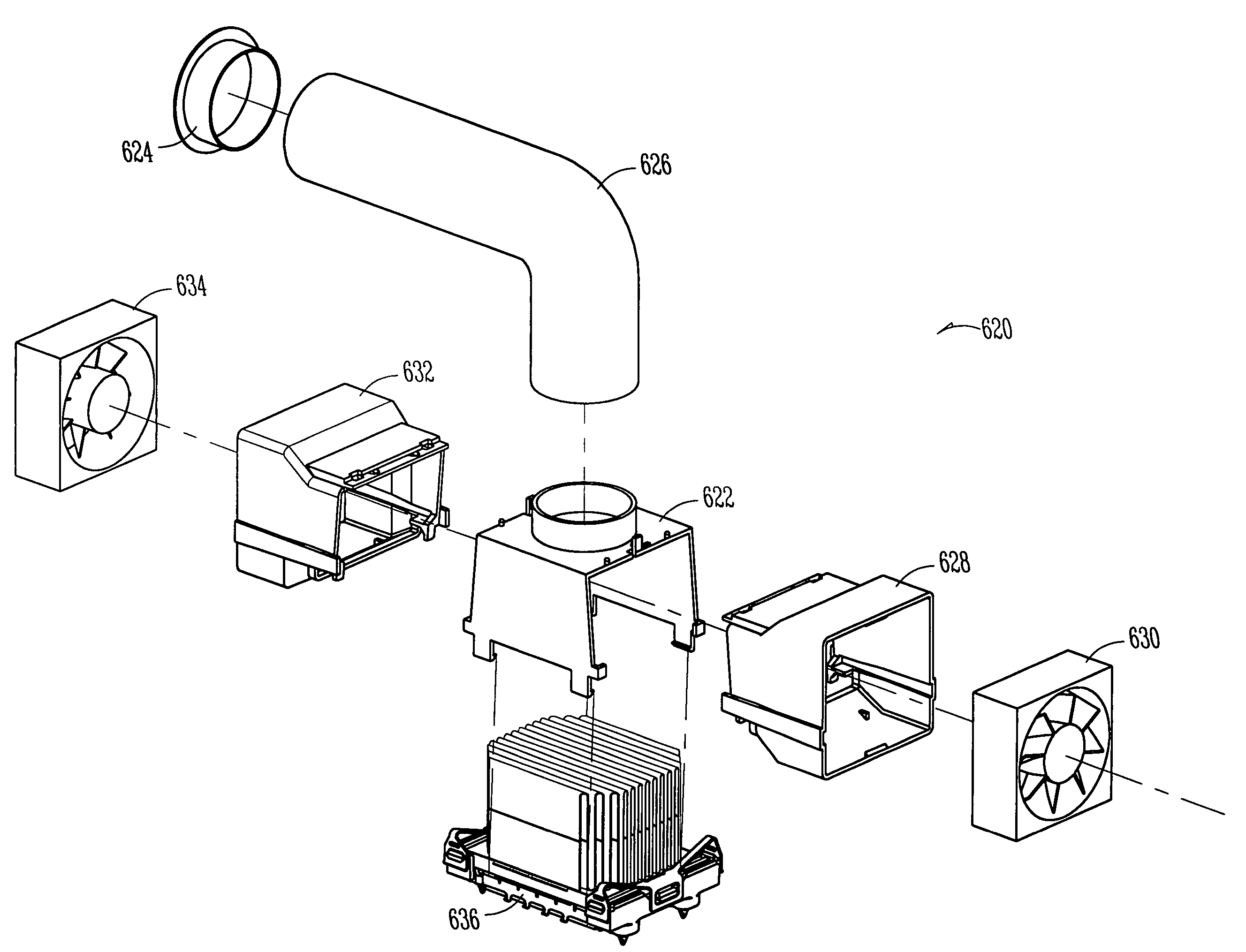
[0027]FIG. 2A is a perspective view of one embodiment of an apparatus for dissipating heat from an electronic device. The apparatus for dissipating heat 200 shown in FIG. 2A comprises a ...


PUM


Abstract

A method and apparatus for dissipating heat from an electronic device is described. The method and apparatus provides a scalable, cost effective, highly efficient, universally applied thermal solution for high heat generating electronic components. In one embodiment, a housing attaches over a heat sink for an electronic device. Various cooling attachments can be attached to this housing to provide a multitude of air flow enhancers. The cooling attachments are designed to provide a thermal engineer or a system integrator with several options for cooling an electronic component. The cooling attachments can be placed in multiple configurations to provide unique thermal solutions. In another embodiment, a kit of parts for a cooling system is provided. The kit of parts includes a housing and a variety of cooling attachments.

Description

RELATED APPLICATION(S)[0001]This application is a Continuation of U.S. application Ser. No. 09 / 615,922 filed on Jul. 13, 2000 now U.S. Pat. No. 6,940,716, which is incorporated herein by reference.TECHNICAL FIELD OF THE INVENTION[0002]The present invention relates generally to the field of electronic devices and, in particular, the present invention relates to thermal management of electronic devices.BACKGROUND[0003]Electronic devices dissipate heat during operation. Thermal management refers to the ability to keep temperature-sensitive elements in an electronic device within a prescribed operating temperature. Thermal management has evolved to address the increased temperatures created within such electronic devices as a result of increased processing speed / power of the electronic devices. Historically, electronic devices were cooled by a natural convection thermal management technique. That is, the cases or packaging of these prior art electronic devices were designed with opening...

Claims


Application Information

Patent Timeline
IPC IPC(8): H05K7/20F28F7/00G06F1/20H01L23/467
CPCG06F1/20H01L23/467H01L2924/0002H01L2924/00
Inventor KORINSKY, GEORGE K.CRAWFORD, CRAIG
Owner INTEL CORP
Why Eureka
Try Eureka