
Autonomous sensor modules for patient monitoring

a sensor module and patient technology, applied in the field of implantable medical devices, can solve the problems of increasing the development and regulatory costs of the device, increasing the burden on quality assurance, and reducing the battery life of the icd to an unacceptable level, and achieves the effect of little or no

Inactive Publication Date: 2010-01-26
PACESETTER INC
View PDF33 Cites 9 Cited by
  • Summary
  • Abstract
  • Description
  • Claims
  • Application Information

AI Technical Summary

Benefits of technology

[0006]Embodiments of the present invention relate to implantable sensors for obtaining hemodynamic data and / or physiologic data. More specifically, embodiments of the present invention enable additional sensor hardware to be added to implantable devices more quickly and less expensively. Additionally, embodiments of the present invention enable such adding of additional sensor hardware with little or no effect on the conventional functions of the implantable device to which the sensor hardware is being added.
[0007]An implantable device according to specific embodiments of the present invention includes a host subsystem and a sensor subsystem. The host subsystem, e.g., configured to deliver pacing pulses and / or defibrillation shocks, includes a host controller (e.g., a processor) and a host power supply (e.g., a battery) to provide power for the host controller and other host components. The sensor subsystem, e.g., configured to obtain hemodynamic data and / or physiologic data, includes a sensor module, a sensor controller (separate from the host controller) to interact with sensor module, and a sensor power supply (separate from the host power supply) to provide power for the sensor module, the sensor controller and other components of the sensor subsystem. Assuming the host subsystem is part of a preexisting and already tested and approved type of implantable device (which may or may not include its own separate sensor circuitry), by keeping the host subsystem and the sensor subsystem electrically isolated from one another, the sensor subsystem's effect on the conventional functions of the host subsystem is reduced, and hopefully minimized. This is accomplished because operation of the sensor subsystem does not affect the host subsystem. Stated another way, a malfunction of the sensor subsystem does not affect the host subsystem. In this manner, the present invention provides for a quicker and less expensive way for the sensor subsystem to be added to the implantable device. The host subsystem and the sensor subsystem are also likely physically isolated from one another (e.g., they may be located on either side of a plane).
[0012]In accordance with alternative embodiments of the present invention, a first hermetically sealed container defines an interior region within which is located the host subsystem, and a second hermetically sealed container (separate from the first container) defines an interior region within which is located the sensor subsystem. In such embodiments, the second container is attached to the separate first container such that the first and second containers can be implanted in a patient as a single implant. The first and second containers can be welded together. Alternatively, the first and second containers can be removably attached to one another (e.g., using screws), thereby enabling the second container (and the sensor subsystem therein) to be detached from the first container and explanted from a patient while leaving the first container (and the host subsystem therein) implanted in the patient.

Problems solved by technology

Integrating additional sensing hardware into an implantable device increases the development and regulatory costs of the device.
For can-based devices, such as ICDs and pacemakers, some of this cost is due to the need to redesign the layout of the internal components in order to accommodate the volume occupied by the additional sensor hardware.
There are also additional burdens to Quality Assurance to verify that the additional sensor hardware does not compromise the conventional functions of the implantable device.
For example, the power requirements of the sensor hardware may be such that it reduces the battery life of an ICD to an unacceptable level.

Method used


Image

  • Autonomous sensor modules for patient monitoring
  • Autonomous sensor modules for patient monitoring
  • Autonomous sensor modules for patient monitoring

Examples


Embodiment Construction

[0025]While the data obtained from implanted sensors may be used by an implanted cardiac device for arrhythmia discrimination, pacing optimization, or the like, such sensor data is often valuable even if it is not used immediately by the implantable device. For example, such sensor data can be stored within the device and then telemetered to an external device which can display the data to a physician and / or analyze the data.

[0026]Embodiments of the present invention enable additional sensing hardware to be added to an implantable device (e.g., a cardiac stimulation device) more quickly and less expensively, with little or no affect on the conventional functions of the implantable device.

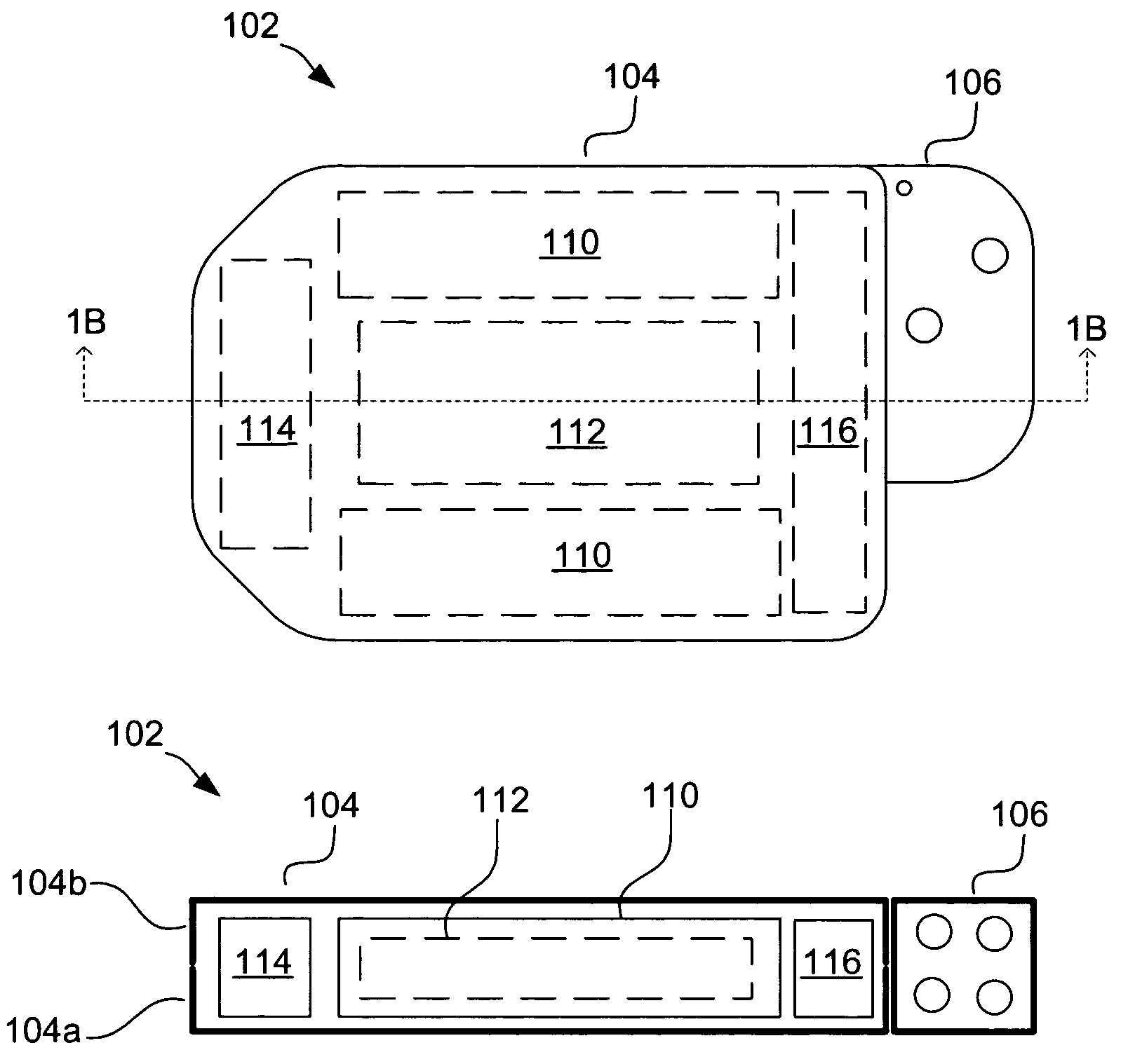
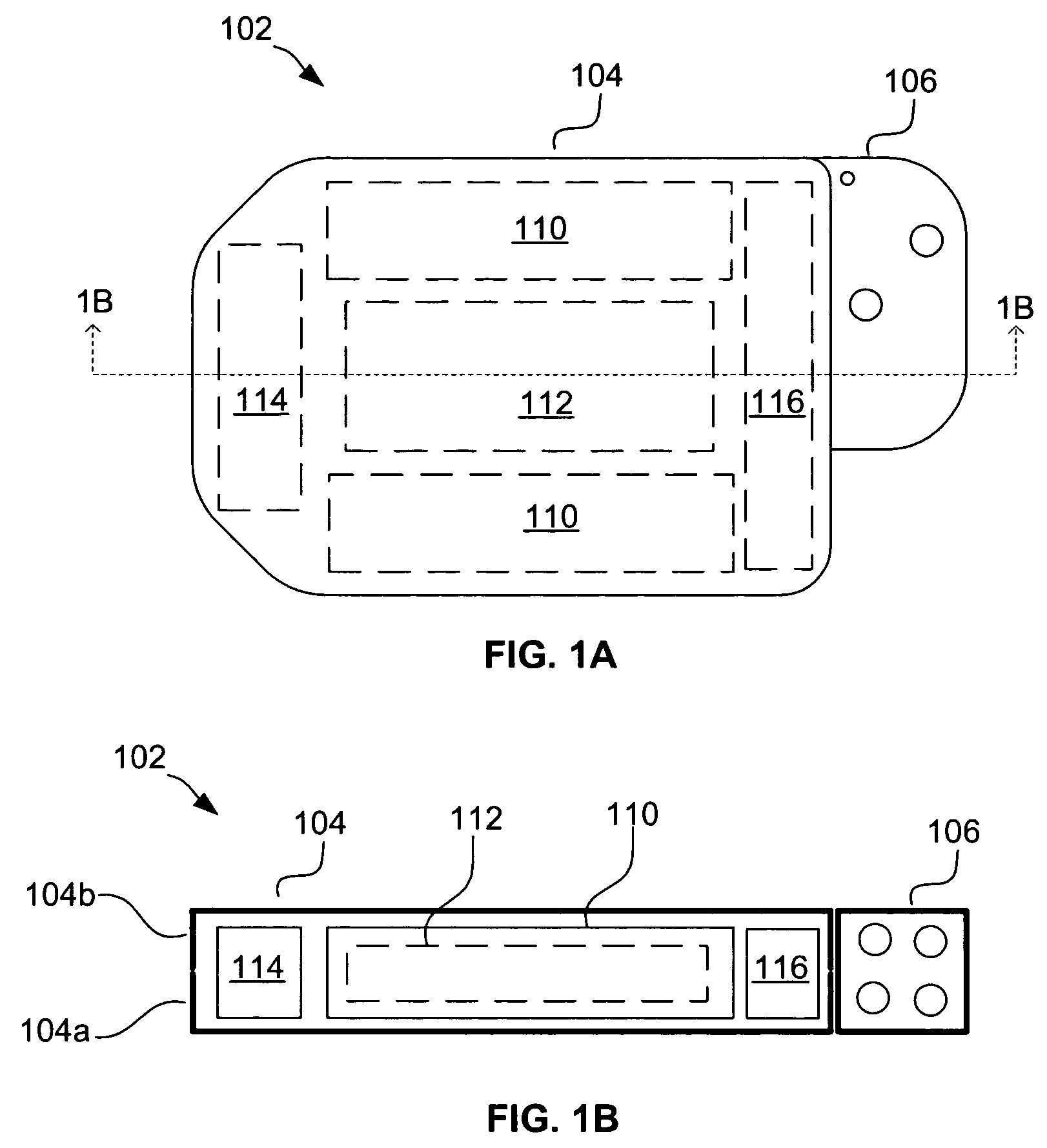
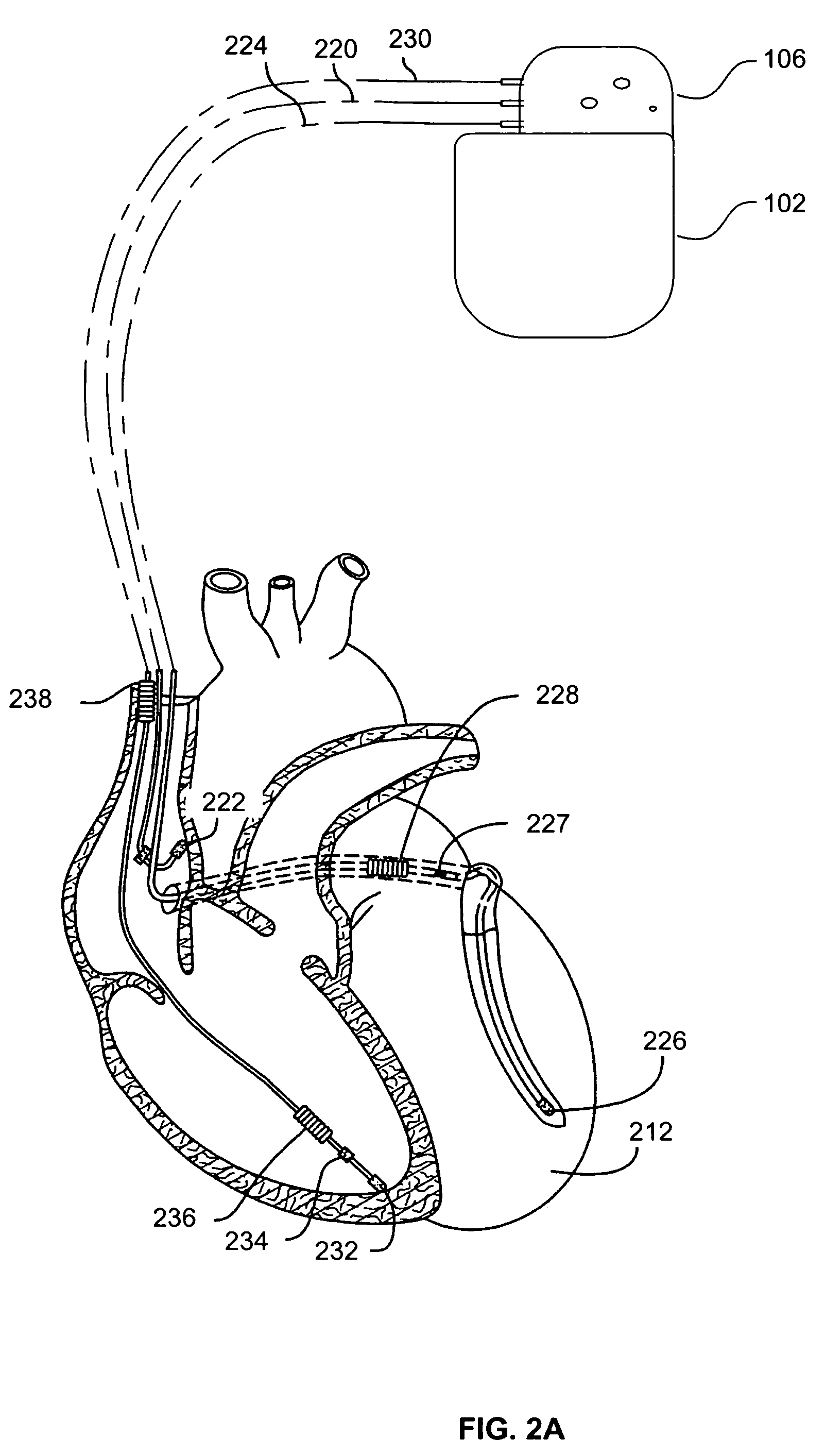
[0027]Referring to FIGS. 1A and 1B, an exemplary implantable cardiac stimulation device 102 is shown. The device 102, which may be an ICD, pacemaker or other stimulation device, includes a container housing 104 (also known as a “can”) and a header 106 (also known as a “connector”). Housed within the...


PUM


Abstract

Embodiments of the present invention relate to implantable sensors for obtaining hemodynamic data and / or physiologic data. More specifically, embodiments of the present invention enable additional sensing hardware to be added into implantable devices more quickly and less expensively. Additionally, embodiments of the present invention enable such adding of additional sensing hardware with little or no effect on the conventional functions of the implantable device to which the sensor hardware is being added.

Description

FIELD OF THE INVENTION[0001]Embodiments of the present invention relate to implantable medical devices that include sensors for obtaining hemodynamic and / or physiologic data.BACKGROUND OF THE INVENTION[0002]Implantable medical devices of the type having electrical circuit components are well known in the medical arts. In one particularly common form, the implantable device is an implantable cardioverter-defibrillator (ICD), a pacemaker, or a combination thereof, having an appropriate electrical power supply and related control circuitry for use in electrically stimulating a patient muscle, such as the heart. Such a device commonly includes a hermetically sealed case or housing within which a power supply and control circuitry are placed. Additionally, one or more conductive leads will typically extend from the housing to a selected muscle structure within a patient.[0003]Recently, there is the desire to chronically implant more physiological sensors within a patient to monitor vario...

Claims


Application Information

Patent Timeline
IPC IPC(8): A61N1/39
CPCA61B5/0031A61N1/025A61N1/375A61N1/36514A61N1/3702A61N1/3962A61N1/37512A61N1/39622
Inventor TURCOTT, ROBERT G.FANG, MICHAEL K.FAYRAM, TIMOTHY A.
Owner PACESETTER INC
Learn More