Die for die casting, method of manufacturing cast product, and cast product

a die casting and die casting technology, applied in the field of die casting, can solve the problems of collision between molten metal components, uneven filling, short filling,

Active Publication Date: 2010-02-02
TOSHIBA CLIENT SOLUTIONS CO LTD
View PDF17 Cites 6 Cited by
  • Summary
  • Abstract
  • Description
  • Claims
  • Application Information

AI Technical Summary

Problems solved by technology

On the other hand, in the right and left product side sections, there is the possibility of shortage of filling, uneven filling, or a crack being caused resulting from incomplete fusion.
However, the molten metal divided by the delta section is joined together in the product section again, and in that process, collision between the molten metal components occurs.
If this gas inclusion occurs, there is the possibility of defective casting called a mold cavity, defective filling, or a molten metal wrinkle being caused.

Method used


Image

  • Die for die casting, method of manufacturing cast product, and cast product
  • Die for die casting, method of manufacturing cast product, and cast product
  • Die for die casting, method of manufacturing cast product, and cast product

Examples


Embodiment Construction

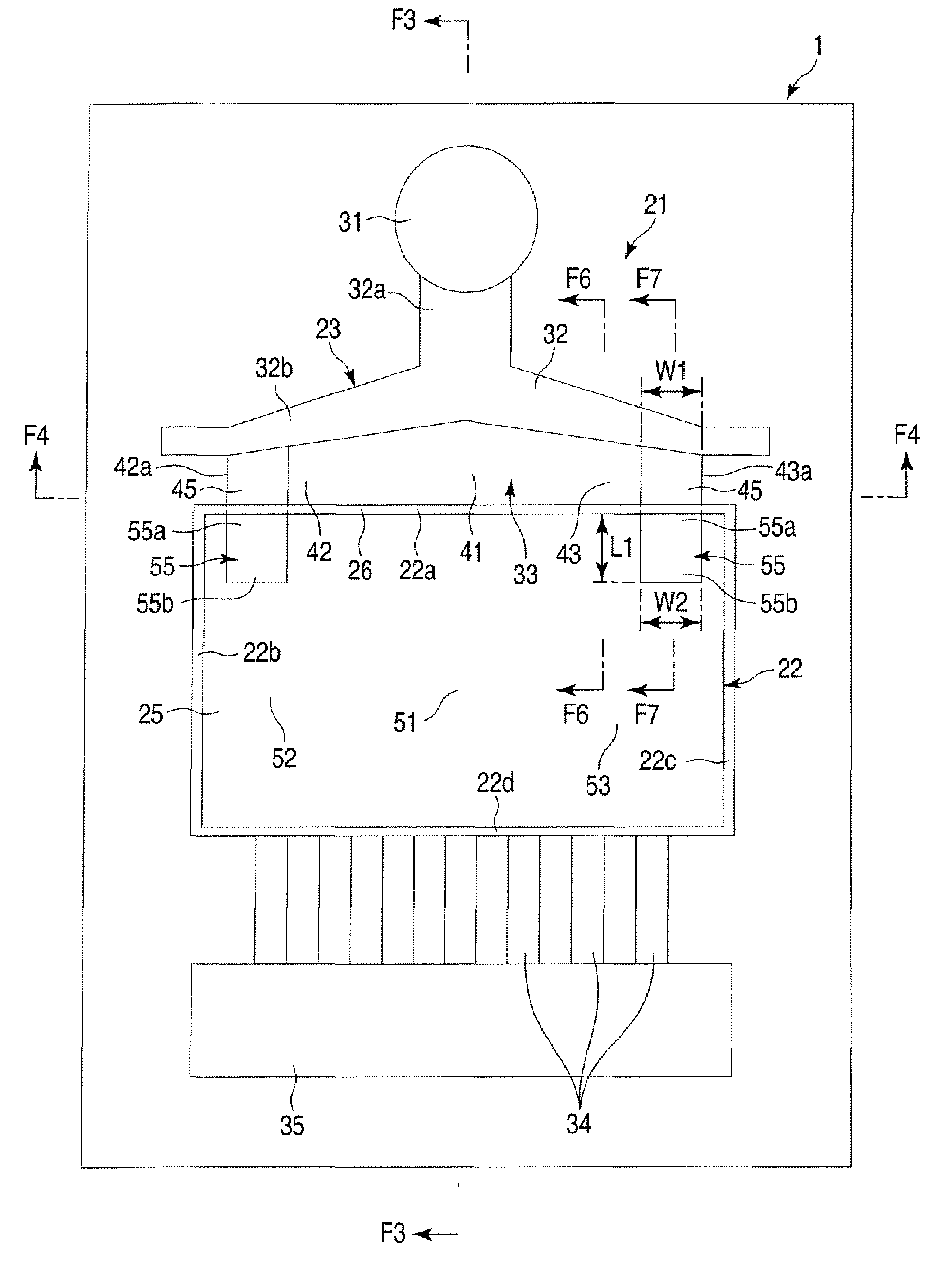
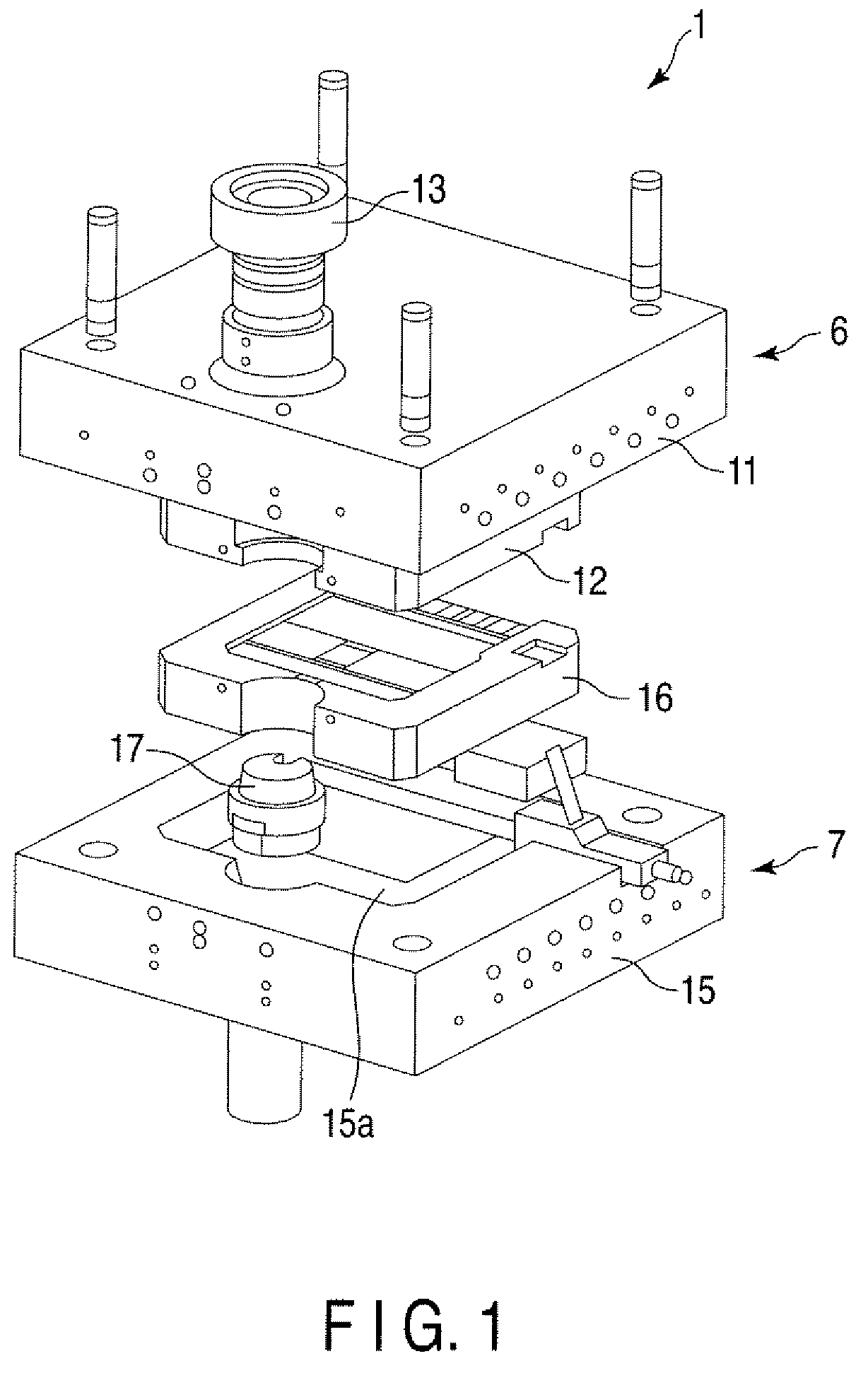
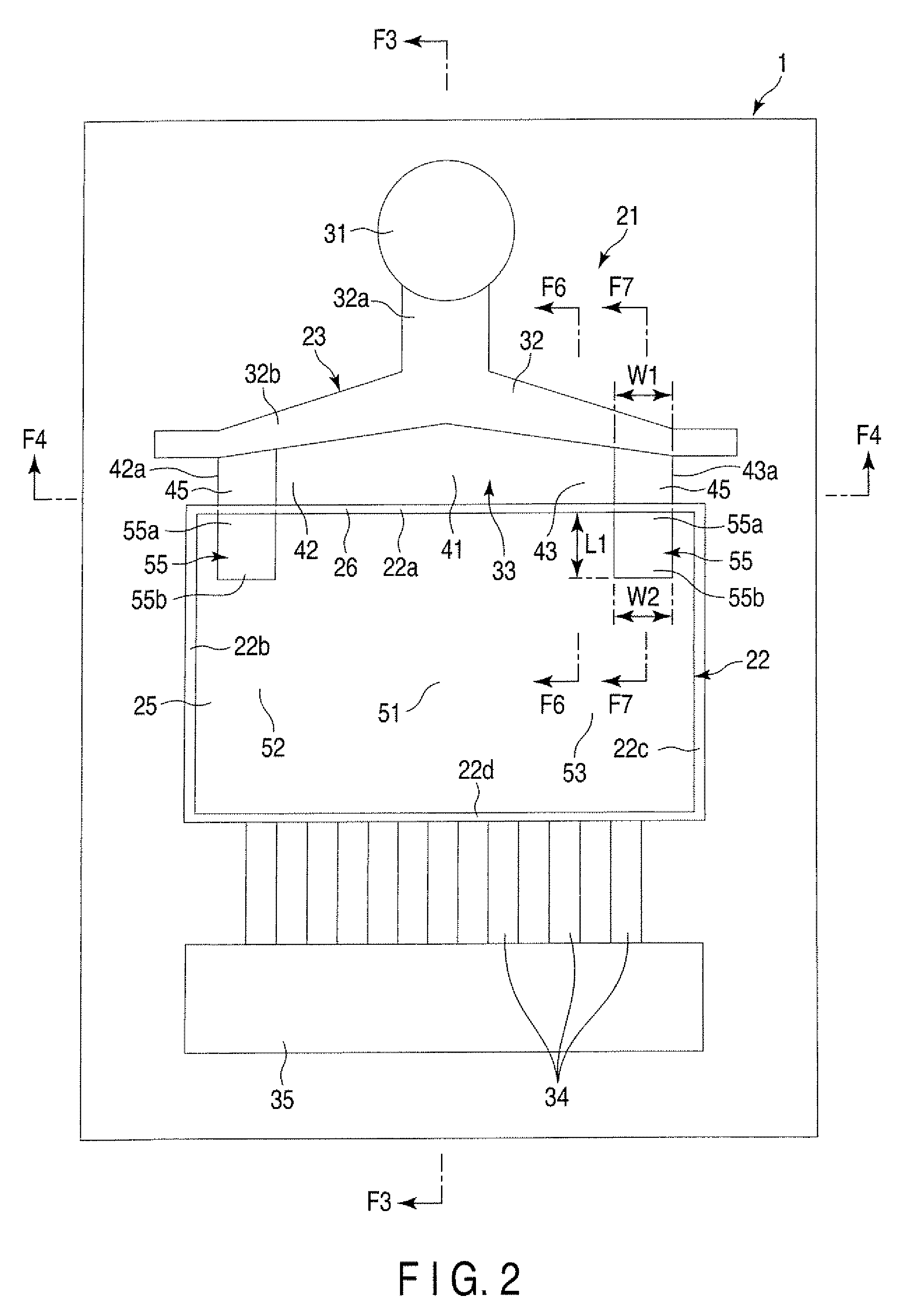
[0020]Various embodiments according to the invention will be described hereinafter with reference to the accompanying drawings. In general, according to one embodiment of the invention, a die for die casting comprises a stationary die, and a movable die to be combined with the stationary. When the movable die is combined with the stationary die, a biscuit section into which molten metal is to be infused, a product section in which a product is to be cast, a runner section which guides the molten metal from the biscuit section toward the product section, and a fin section which is provided between the runner section and the product section, and in which a thickness of the fin section decreases in a direction closer to the product section are formed between the stationary die and the movable die. The fin section is extended from one end part to the other end part of the product section in a direction intersecting a stream direction of the molten metal, and includes a fin central secti...


PUM

PropertyMeasurementUnit
width W1aaaaaaaaaa
angle of inclinationaaaaaaaaaa
length L1aaaaaaaaaa

Abstract

According to one embodiment, a die includes a stationary die, and a movable die. A fin section provided between a runner section and a product section is extended from one end part to the other end part of the product section in a direction intersecting a stream direction of molten metal, and includes a fin central section opposed to a biscuit section in the stream direction of the molten metal, and a fin side section on a side of the fin central section. The fin side section includes a fin thick part formed thicker than a thickness of the fin central section. The fin thick part is extended to a boundary between the fin section and the product section. The product section includes a product thick part connected to the fin thick part in a region opposed to the fin thick part.

Description

CROSS-REFERENCE TO RELATED APPLICATIONS[0001]This application is based upon and claims the benefit of priority from Japanese Patent Application No. 2007-323945, filed Dec, 14, 2007, the entire contents of which are incorporated herein by reference.BACKGROUND[0002]1. Field[0003]One embodiment of the present invention relates to a technique associated with die casting.[0004]2. Description of the Related Art[0005]A die-casting die of the cold-chamber die casting system is provided with a fan gate for guiding molten metal to a product section (i.e., section in which a product is to be cast) inside the die. The fan gate includes a biscuit section for receiving molten metal from an injection apparatus of a casting machine, a runner section for guiding the molten metal from the biscuit section to the product section, and a fin section for accelerating the flow speed of the molten metal by sharply reducing the thickness.[0006]The product section includes a product central section correspond...

Claims


Application Information

Patent Timeline
Patent Type & Authority Patents(United States)
IPC IPC(8): B22D17/08B22D17/20
CPCB22D17/22
Inventor HIRAO, HIROAKI
Owner TOSHIBA CLIENT SOLUTIONS CO LTD
Why Eureka
Try Eureka