
Methods of charging battery packs for cordless power tool systems

a technology of power tools and battery packs, applied in the direction of electric vehicles, transportation and packaging, electric generators, etc., can solve the problems of complex charge circuitry and complicated charging circuitry

Inactive Publication Date: 2010-02-02
BLACK & DECKER INC
View PDF6 Cites 1232 Cited by
  • Summary
  • Abstract
  • Description
  • Claims
  • Application Information

AI Technical Summary

Benefits of technology

The present invention provides methods for charging a battery pack. The method involves inserting the battery pack into a charger and performing initial checks of cell voltage and pack temperature. The cells are then charged at a constant current level until they reach a full charge voltage window. The charge is terminated once all cells are within the full charge voltage window. The method also allows for selective discharging of individual cells while other cells continue to charge. The technical effects of the invention include improved charging efficiency, reduced charging time, and improved battery performance.

Problems solved by technology

This requires complicated or complex charge circuitry, especially when charging a battery pack with a number of serially connected cells with voltages of each cell potentially being at different levels.

Method used


Image

  • Methods of charging battery packs for cordless power tool systems
  • Methods of charging battery packs for cordless power tool systems
  • Methods of charging battery packs for cordless power tool systems

Examples


Embodiment Construction

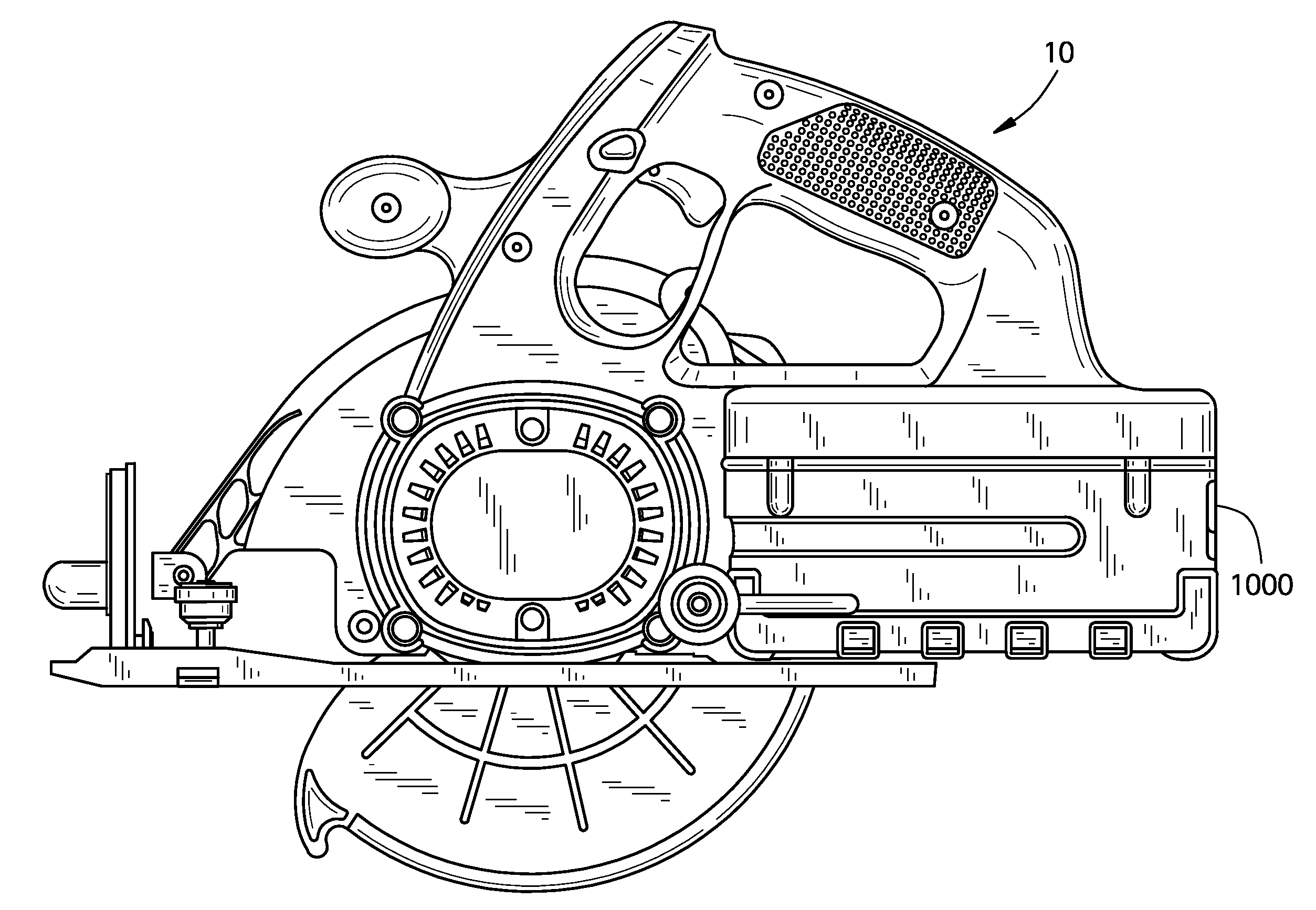
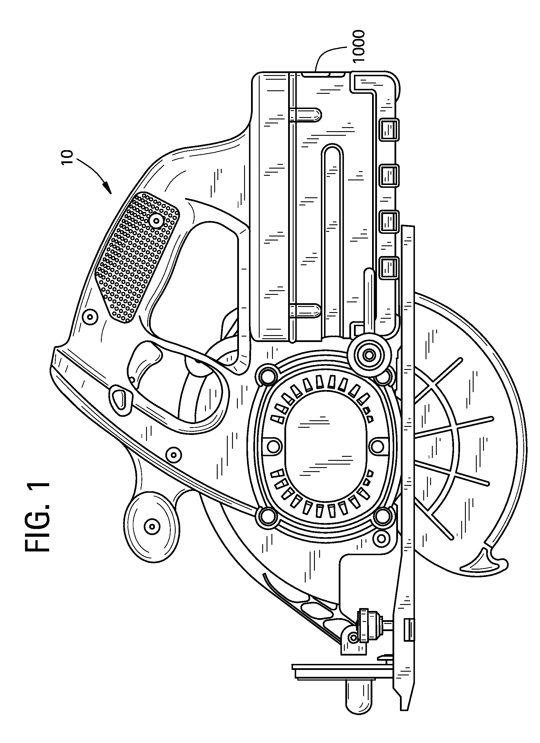
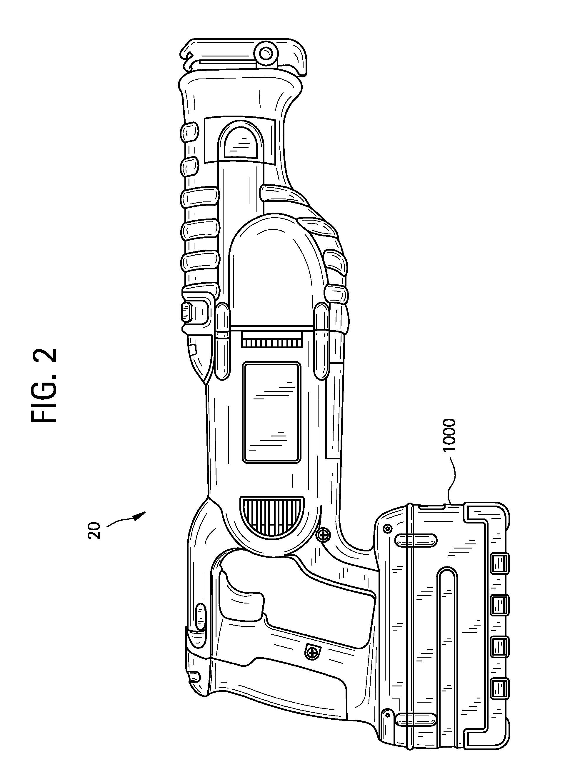
[0020]Prior to describing the example battery charge methodologies, the inventors initially provide with reference to FIGS. 1-9 an overview of a cordless power tool system including an example battery pack and battery charger, an example block diagram between pack and charger and example cell configurations with the battery pack of the cordless power tool system. The overview provides better context for the example battery charging methodologies described thereafter.

[0021]FIGS. 1-3 illustrate illustrative cordless power tools of a cordless power tool system in accordance with an example embodiment of the present invention. The battery charging methods described in further detail hereafter may be employed to charge battery packs designed for powering a system of cordless power tools. Example cordless power tools are shown to include, by way of examples only, a circular power saw 10 (FIG. 1), a reciprocating saw 20 (FIG. 2) and a drill 30 (FIG. 2). The tools 10, 20 and 30 each may inc...


PUM


Abstract

In a method of charging a battery pack, the pack is inserted in a charger and an initial set of checks of cell voltage and pack temperature is performed. Once the initial set of checks is satisfied, the cells may be charged at a first constant current level. The first constant current level is adjusted to one or more lower levels of constant current until cell voltages of all the cells are within a full charge voltage window. The voltage window is defined between a minimum full charge cell voltage level and a maximum full charge cell voltage level. The charge may be terminated once all of the cells are within the full charge voltage window.

Description

PRIORITY STATEMENT[0001]This U.S. non-provisional patent application claims the benefit under 35 U.S.C. §119(e) to U.S. Provisional Patent Application Ser. No. 60 / 731,500, filed Oct. 31, 2005, the entire contents of which are hereby incorporated by reference herein.BACKGROUND[0002]1. Field[0003]Example embodiments relate generally to methods of charging battery packs for cordless power tools.[0004]2. Description of Related Art[0005]Conventional charge algorithms for Li-ion battery packs typically employ a constant current / constant voltage (CC / CV) charge algorithm in which the charge current is held at a constant level for a period of time, while the battery pack increases in voltage to a set voltage threshold level, typically about 90% state of charge. At that point, the pack voltage is maintained at a constant voltage level while the current gradually decreases to a lower level so as to complete the charge.[0006]For charging conventional Li-ion battery packs, the power supply (char...

Claims


Application Information

Patent Timeline
Patent Type & Authority Patents(United States)
IPC IPC(8): H02J7/04H02J7/16
CPCH02J7/0011H02J7/041H02J2007/0098H02J7/0071H01M10/4257H02J7/0036Y02E60/10H02J7/04H02J7/00
Inventor EMBREY, JANET M.TRINH, DANH T.
Owner BLACK & DECKER INC
Learn More