Method for quickly supplementing electric energy of electric vehicle and power supply unit thereof

An electric vehicle and supplementary electricity technology, applied in the field of transportation, can solve the problems of not optimistic application prospects, restrictions on the popularization of electric vehicles, and increased maintenance costs

Active Publication Date: 2011-06-01
尹学军
View PDF5 Cites 50 Cited by
  • Summary
  • Abstract
  • Description
  • Claims
  • Application Information

AI Technical Summary

Problems solved by technology

There is a common problem in pure electric vehicles powered by rechargeable batteries. The charging time of ordinary vehicle batteries takes several hours, and it cannot quickly complete energy replenishment at gas stations like various oil and gas fuels. This greatly limits the popularity of electric vehicles.
In order to solve the above problems, the patent application No. 200810006771.6 proposes a method and device for quickly replacing large battery packs. These methods generally use so-called high-voltage battery packs or full-voltage battery packs as replacement units. For the convenience of replacement, the weight of the battery Because electric vehicles of different models and brands have different shapes and their internal spaces are quite different, the use of large-scale high-voltage batteries with large dimensions makes it difficult to standardize the specifications and models of batteries objectively, and it is impossible to use a limited number of The type of battery is suitable for most models on the market, and the battery packs of different sizes and shapes also increase the difficulty of building an electric energy supplementary mechanism s...

Method used


Image

  • Method for quickly supplementing electric energy of electric vehicle and power supply unit thereof
  • Method for quickly supplementing electric energy of electric vehicle and power supply unit thereof
  • Method for quickly supplementing electric energy of electric vehicle and power supply unit thereof

Examples


Embodiment 1

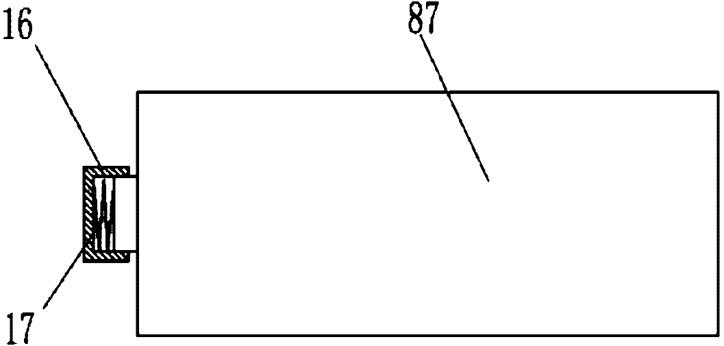
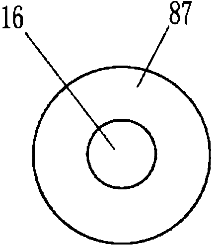
[0078] like figure 1 , figure 2 The shown standard battery unit of the present invention comprises a battery basic unit 87, and the anode of the battery basic unit 87 is provided with an elastic telescopic structure 17, and the elastic telescopic structure 17 is made of a spring made of a metal good conductor material, in order to prevent foreign matter from falling into the spring 17 Inside, the front end of the spring 17 is also provided with an electrode cap 16 made of metal good conductor material, the electrode cap and the anode can slide relative to each other, but due to the connection of the spring 17, the electrode cap and the anode always maintain a good communication state. The cathode of the battery basic unit in this example adopts a conventional flat bottom structure.

[0079] The battery basic unit 87 in this example can be any in various batteries such as lead-acid storage battery, or lead-acid colloidal battery, or metal hydride / nickel battery, or lithium io...

Embodiment 2

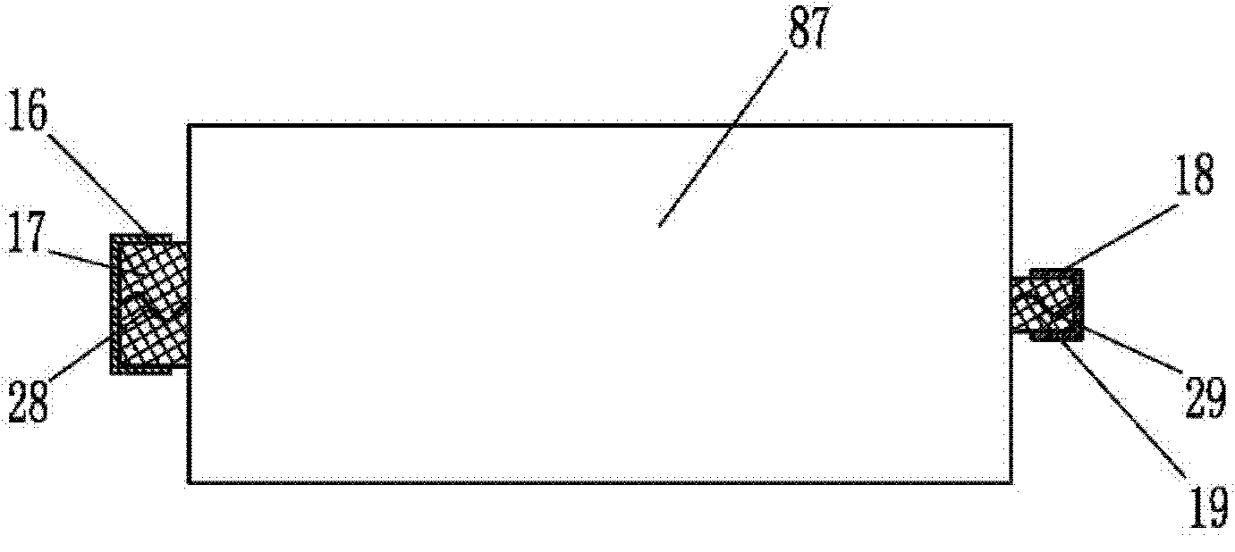
[0083] like image 3 , Figure 4 The difference between the standard battery unit of the present invention shown in Embodiment 1 is that the two ends of the battery basic unit 87 are respectively provided with electrodes protruding from their corresponding end faces, and the anode and cathode are respectively provided with elastic stretchable structures 17 and 19. The elastic telescopic structures 17 and 19 are all made of elastic rubber material in the example. Wherein, the elastic telescopic structure 17 is provided with an electrode cap 16 made of a metal good conductor material, and the electrode cap 16 is connected to the anode of the battery basic unit 87 through a wire 28; the elastic telescopic structure 19 is provided with an electrode made of a metal good conductor material. The cap 18 and the electrode cap 18 are connected to the cathode of the battery basic unit 87 through a wire 29 . Pay attention to the connection strength between the electrode cap and the elec...

Embodiment 3

[0087] like Figure 5 , Image 6 The difference between the shown standard battery unit of the present invention and the second embodiment is that in this example, the cylindrical battery basic unit 87 is used as an example for illustration, the elastic telescopic structures 17 and 19 are all made of metal springs, and the electrode cap 16 and the electrode cap The shape of the cross-sectional profile of 18 is set to a square. In addition, in order to prevent the standard battery from being damaged due to excessive wear and tear during repeated loading and unloading, the battery basic unit 87 is also provided with a wear-resistant cushion 15. In this example, the wear-resistant cushion 15 is made of wear-resistant and heat-resistant engineering plastics production.

[0088] Since the standard battery unit described in this example includes the wear-resistant pad 15, it can effectively protect the standard battery unit itself and reduce the wear on the shell of the standard b...


PUM


Abstract

The invention relates to a method for quickly supplementing electric energy of an electric vehicle and a power supply unit thereof. The method is characterized in that a rechargeable battery pack is arranged on the electric vehicle, and a battery replacement unit, a charging library and a battery library are arranged in a power plant, wherein the rechargeable battery pack comprises a battery box and standardized standard battery units; a battery chamber is internally provided with a plurality of standard battery unit stations; guide rails are installed along with the load direction of the standard battery units; when the standard battery units operate, the standard battery units are arranged in the battery box and can smoothly load and unload in the battery box along the guide rails; after the standard battery units are in place, battery electrodes contact with electrode touching rails which are connected mutually by fixed series-parallel circuits; and the rechargeable battery pack is assembled on the electric vehicle. When it is required to supplement the electric energy, the electric vehicle enters the power plant, so that the standard battery units which are lack of electric energy are replaced by the standard battery units which are charged in the battery box. The power supply unit provided by the invention is convenient to use and reliable in performance, especially applied to quickly supplementing the electric energy for the electric vehicle, and having broad application prospects.

Description

technical field [0001] The invention belongs to the field of transportation and relates to the energy supply of electric vehicles, in particular to a method for rapidly supplementing electric energy of electric vehicles and a corresponding power supply device. Background technique [0002] With the advancement of science and technology and the development of the economy, people's production and living space is constantly expanding, and various vehicles have become an indispensable means of transportation for people to travel. In the past, the power energy of vehicles mainly came from petroleum products and various gases. However, with the decreasing of oil and gas resources and the increasingly serious problems of noise pollution, air pollution and global warming, it is necessary to develop and utilize environmentally friendly alternative energy sources, reduce CO2 Emissions have become the consensus of the people. In this context, electric energy, as an environmentally fri...

Claims


Application Information

Patent Timeline
IPC IPC(8): H01M10/44H01M2/10H01M10/00H01M4/00B60L50/64
CPCY02T90/128Y02T90/14Y02T90/163B60L2200/18B60L11/1879B60L11/1801Y02E60/12B60L11/1824B60S5/06Y02T10/705B60L11/1877B60L2200/12H01M2/1077B60L11/1822B60L2230/16B60L11/007Y02T90/124B60L3/0046B60L3/0069B60L2240/545H01M2/1083Y02T10/7005B60L2270/145B60L2200/26B60L11/1874Y02T10/7072B60L50/53B60L50/20B60L53/80B60L58/26B60L50/66B60L50/64B60L53/305B60L58/27B60L58/19B60L53/302Y02T10/70Y02T90/12Y02T90/16Y02E60/10H01M50/249H01M50/209H01M50/213H01M50/242H01M50/227H01M50/244
Inventor 尹学军孔祥斐尹柏婷
Owner 尹学军
Why Eureka
Try Eureka