High contrast tip-enhanced Raman spectroscopy

a raman spectroscopy and high contrast technology, applied in the field of spectroscopy, can solve the problems of small contrast insufficient scanning ter, drastic increase in measurement time, and decrease in measurement accuracy, and achieve the effect of enhancing the contrast-ratio

Inactive Publication Date: 2010-02-02
AKRON THE UNIV OF
View PDF4 Cites 18 Cited by
  • Summary
  • Abstract
  • Description
  • Claims
  • Application Information

AI Technical Summary

Benefits of technology

[0006]The present invention relates generally to the field of spectroscopy, and more particularly to tip-enhanced Raman spectroscopy that provides an enhanced contrast-ratio of a near-field Raman signal to a background signal. The near-field Raman signal is captured from a small volume of material near a metal-coated tip, thereby achieving submicron lateral resolution.

Problems solved by technology

This small contrast is insufficient for scanning TERS and will require subtraction of the far-field signal to achieve useful results.
Such corrections will introduce significant uncertainty, strongly decrease the accuracy of the measurements, and drastically increase measurement time.
However, the proposed top-illumination geometry poses several problems to commercialization.
It is neither simple nor convenient to work in this configuration.
This geometry has a number of disadvantages: (i) it restricts the near-field Raman signal to the edges of the particle; (ii) it limits lateral resolution to at least the size of the particle or even larger (approximately 100 nm); (iii) the maximum enhanced signal from the Si surface closest to the particle is lost (shadowed by the particle).

Method used


Image

  • High contrast tip-enhanced Raman spectroscopy
  • High contrast tip-enhanced Raman spectroscopy
  • High contrast tip-enhanced Raman spectroscopy

Examples


Embodiment Construction

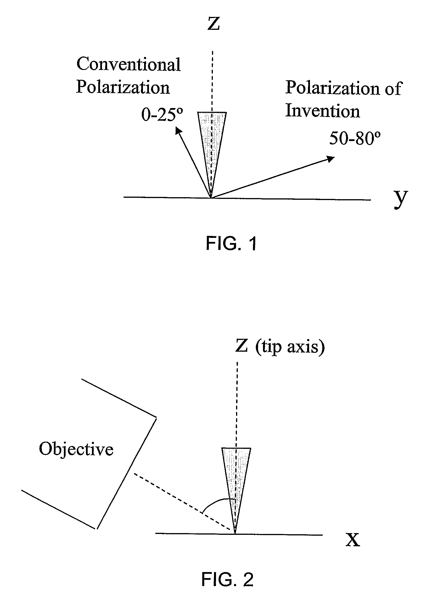
[0021]The present invention relates generally to the field of spectroscopy, and more particularly to tip-enhanced Raman spectroscopy that provides an enhanced contrast-ratio of a near-field Raman signal to a background signal. The near-field Raman signal is captured from a small volume of material near a metal-coated tip thereby achieving submicron lateral resolution.

[0022]Certain terminology is used herein for convenience only and is not to be taken as a limitation on the present invention.

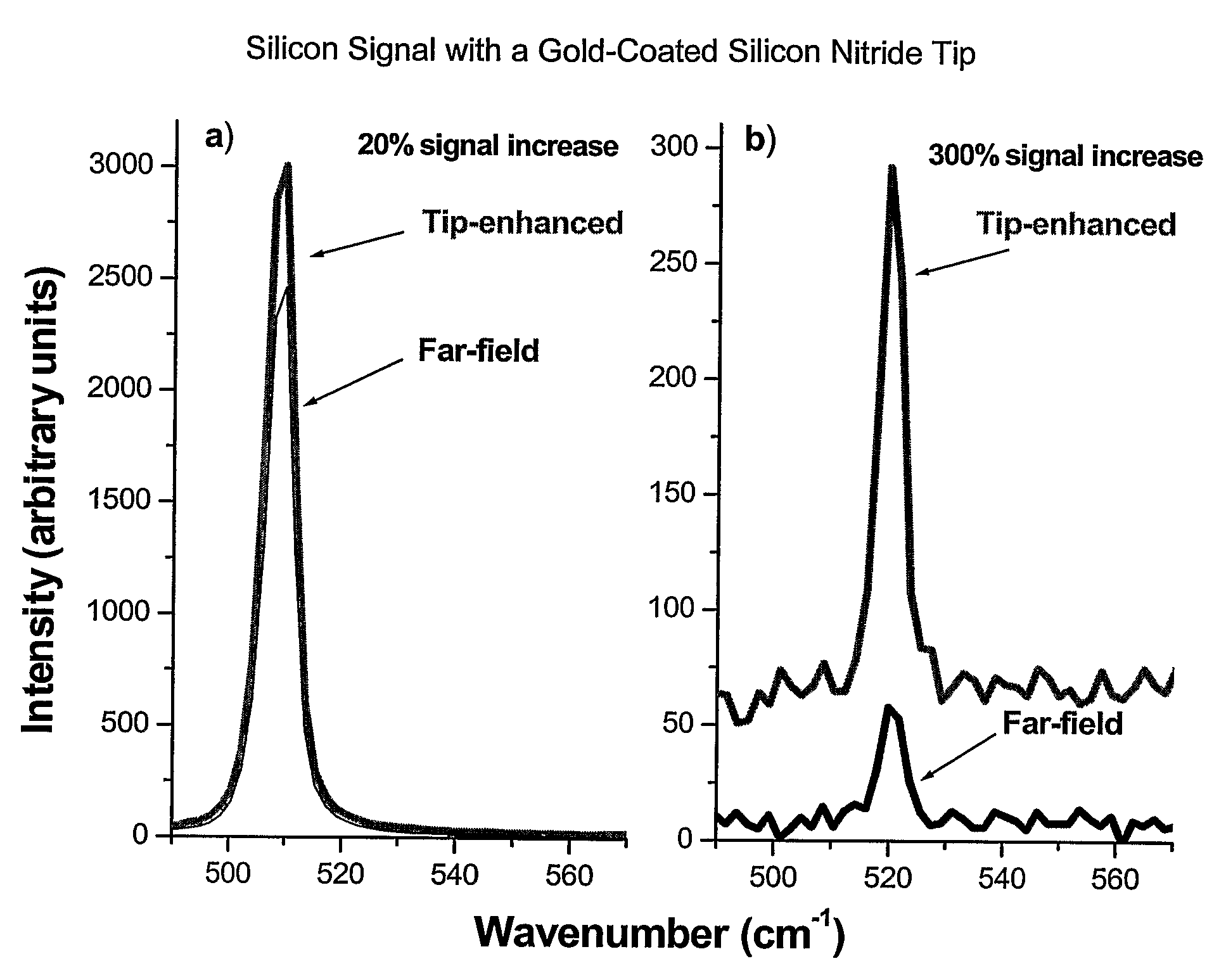
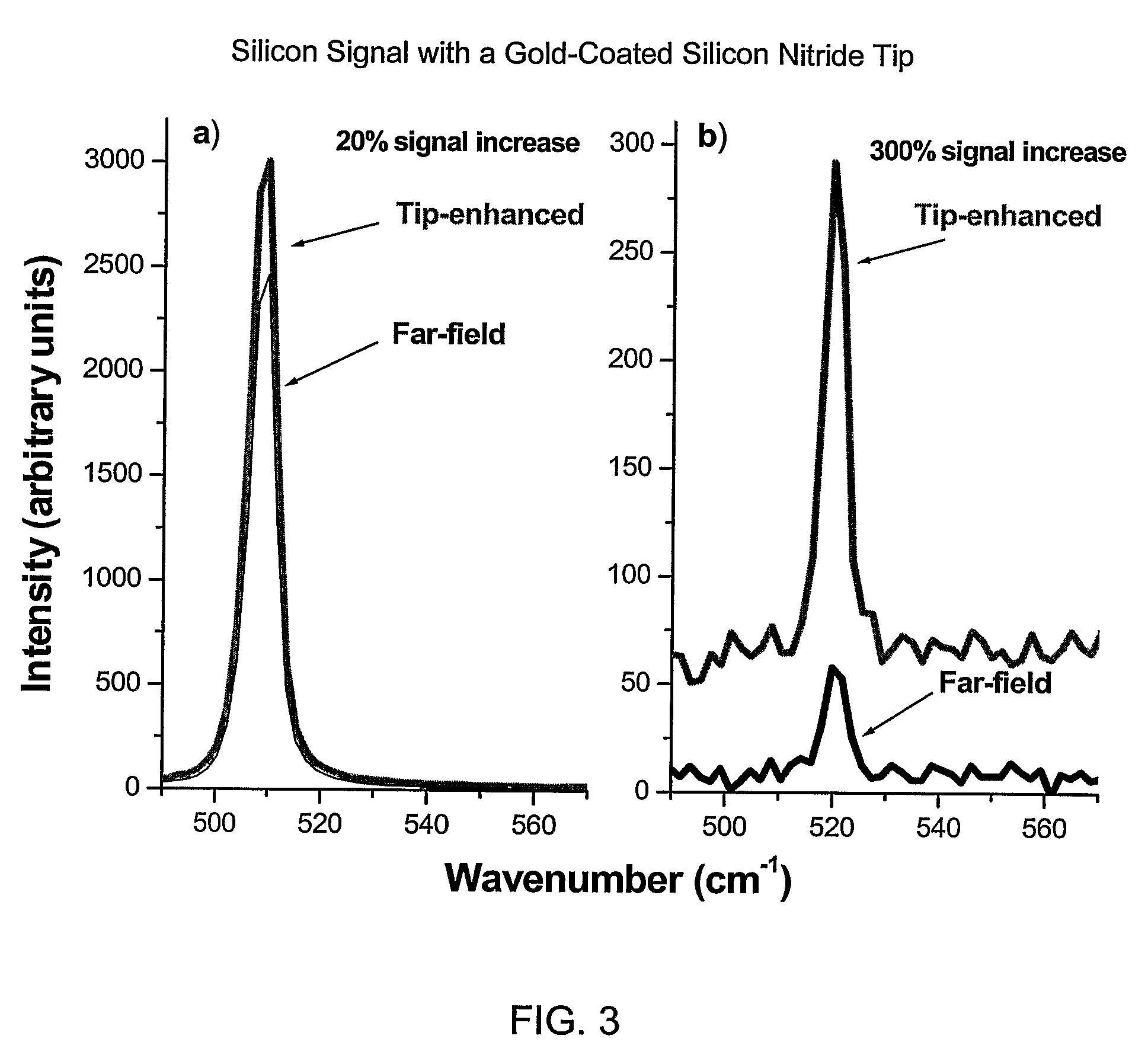
[0023]The contrast ratio is the ratio of the near-filed signal (total signal minus the far-field signal) to the far-field signal and can be represented mathematically as: C=Inear / Ifar≈(Itotal−Ifar) / Ifar=Itotal / (Ifar−1), where I is the signal intensity. To achieve the desired contrast ratio, the enhancement factor of the tip is to be maximized, the far-field intensity is to be minimized, or a combination of both. The enhancement factor refers to the increase in near-field Raman signal due to metal...


PUM

PropertyMeasurementUnit
angleaaaaaaaaaa
angleaaaaaaaaaa
orientation angleaaaaaaaaaa

Abstract

The present invention relates generally to the field of spectroscopy, and more particularly to tip-enhanced Raman spectroscopy that provides an enhanced contrast-ratio of a near-field Raman signal to a background signal. The near-field Raman signal is captured from a small volume of material near a metal-coated tip thereby achieving submicron lateral resolution.

Description

FIELD OF THE INVENTION[0001]The present invention relates generally to the field of spectroscopy, and more particularly to tip-enhanced Raman spectroscopy that provides an enhanced contrast-ratio of a near-field Raman signal to a background signal. The near-field Raman signal is captured from a small volume of material near a metal-coated tip, thereby achieving submicron lateral resolution.BACKGROUND OF THE INVENTION[0002]The general concept of Raman signal enhancement near a sub-micrometer-sized metal particle disposed at a tip has been proposed and realized. The presence of a metal particle at the tip enhances the strength of an electrical field of light, thereby inducing enhancement of that portion of the total Raman signal within 10 to 20 nm of the particle's surface. This portion of the total Raman signal adjacent to the surface of the metal particle is referred to herein as the near-field signal and the portion of the total Raman signal outside this region is the far-field sig...

Claims


Application Information

Patent Timeline
Patent Type & Authority Patents(United States)
IPC IPC(8): G01J3/44G01N21/65
CPCG01N21/658G01N21/6445
Inventor SOKOLOV, ALEXEI P.KISLIUK, ALEXANDERMEHTANI, DISHAHARTSCHUH, RYAN D.LEE, NAM-HEUI
Owner AKRON THE UNIV OF
Why Eureka
Try Eureka