Receiver for an optical signal

a technology for optical signals and receivers, applied in the field of optical communication systems, can solve the problems of optimum adaptation, bit error rate not minimized, optical signal distorted with so-called inter-symbolic interference, etc., and achieve the effects of improving receivers, reducing bit error rates, and increasing the corruption of input signals

Inactive Publication Date: 2010-02-02
RPX CORP
View PDF3 Cites 2 Cited by
  • Summary
  • Abstract
  • Description
  • Claims
  • Application Information

AI Technical Summary

Benefits of technology

[0011]One advantage of the invention is the fact that the eye monitor allows a “fine-tuning” of the adapted threshold signal and / or the adapted coefficient. This optimization results in a minimized bit error rate and thereby in an improved receiver.
[0012]Another advantage of the invention is the fact that only a minimum number of decision flip-flops are necessary to implement the decision feedback equalizer and the eye monitor. In particular, only two decision flip-flops are used to realize the receiver. This minimum number of decision flip-flops does not further increase the corruption of the distorted input signal. This advantage becomes even more apparent if a decision feedback equalizer with more than one tap is regarded.
[0013]Another advantage of the invention is the fact that no forward error correction is necessary for obtaining an error signal required for the adaptation of the threshold signal and / or the coefficient signal. This reduces the number of electrical circuits of the receiver resulting in an improved of the bit error rate.
[0014]In an advantageous embodiment of the invention, a control unit is provided for influencing the first threshold signal and / or the first coefficient depending on the outputs of the decision feedback equalizer and the eye monitor. The control unit allows to implement given schemes for the generation of the first threshold signal and / or the first coefficient. In particular, different schemes may be used for an upper eye and a lower eye of an eye diagram of the eye monitor. Thereby, it is possible to optimize the generation of the first threshold signal and / or the first coefficient depending on the upper or lower eye.

Problems solved by technology

Instead, the pulses overlap what leads to a distorted optical signal with so-called inter-symbol interferences.
However, the known algorithms do not provide an optimum adaptation so that a resulting bit error rate is not minimized.
Due to the electrical input circuits of these four decision flip-flops, the distorted signal becomes even more corrupted and the bit error rate increases.

Method used


Image

  • Receiver for an optical signal
  • Receiver for an optical signal
  • Receiver for an optical signal

Examples


Embodiment Construction

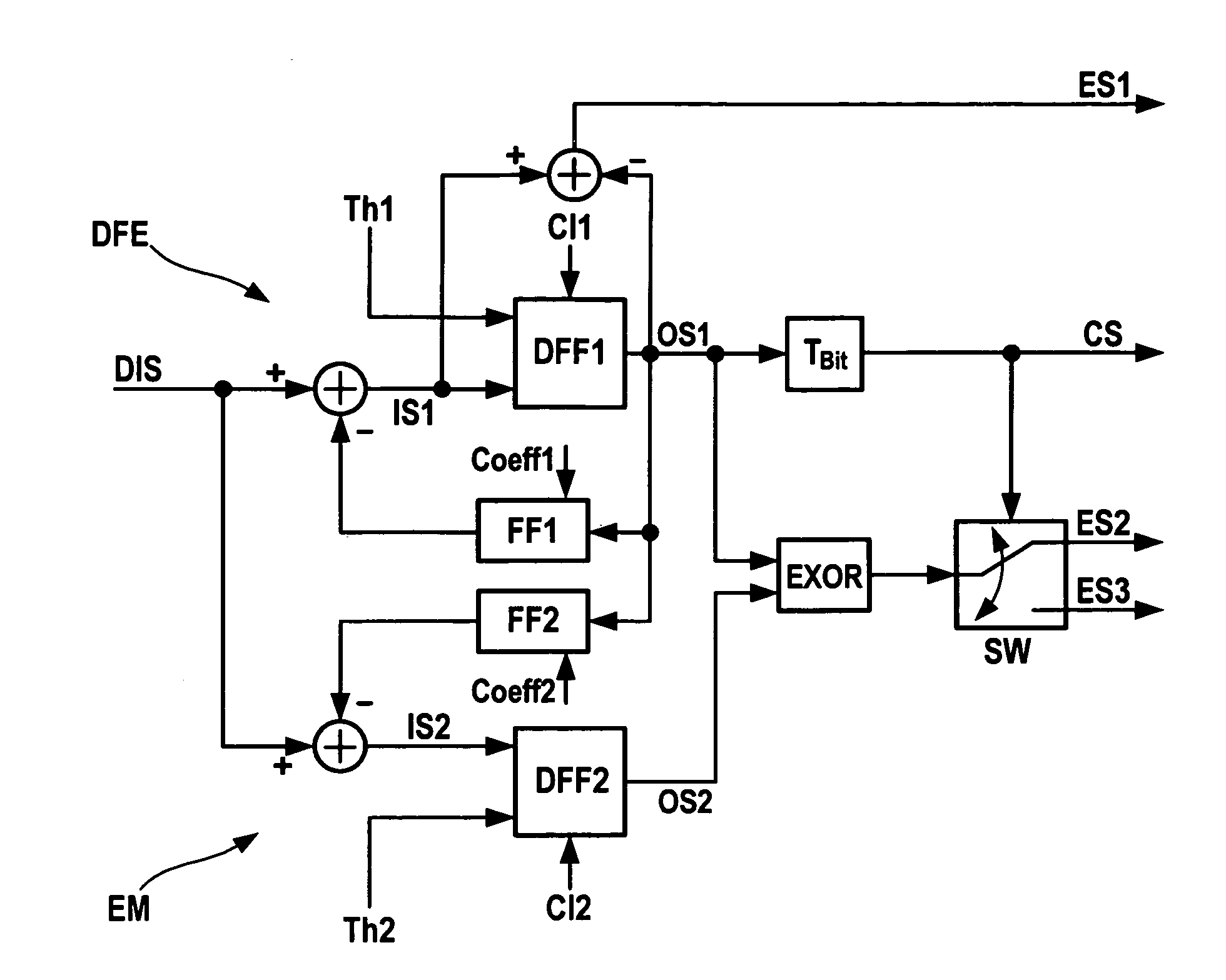
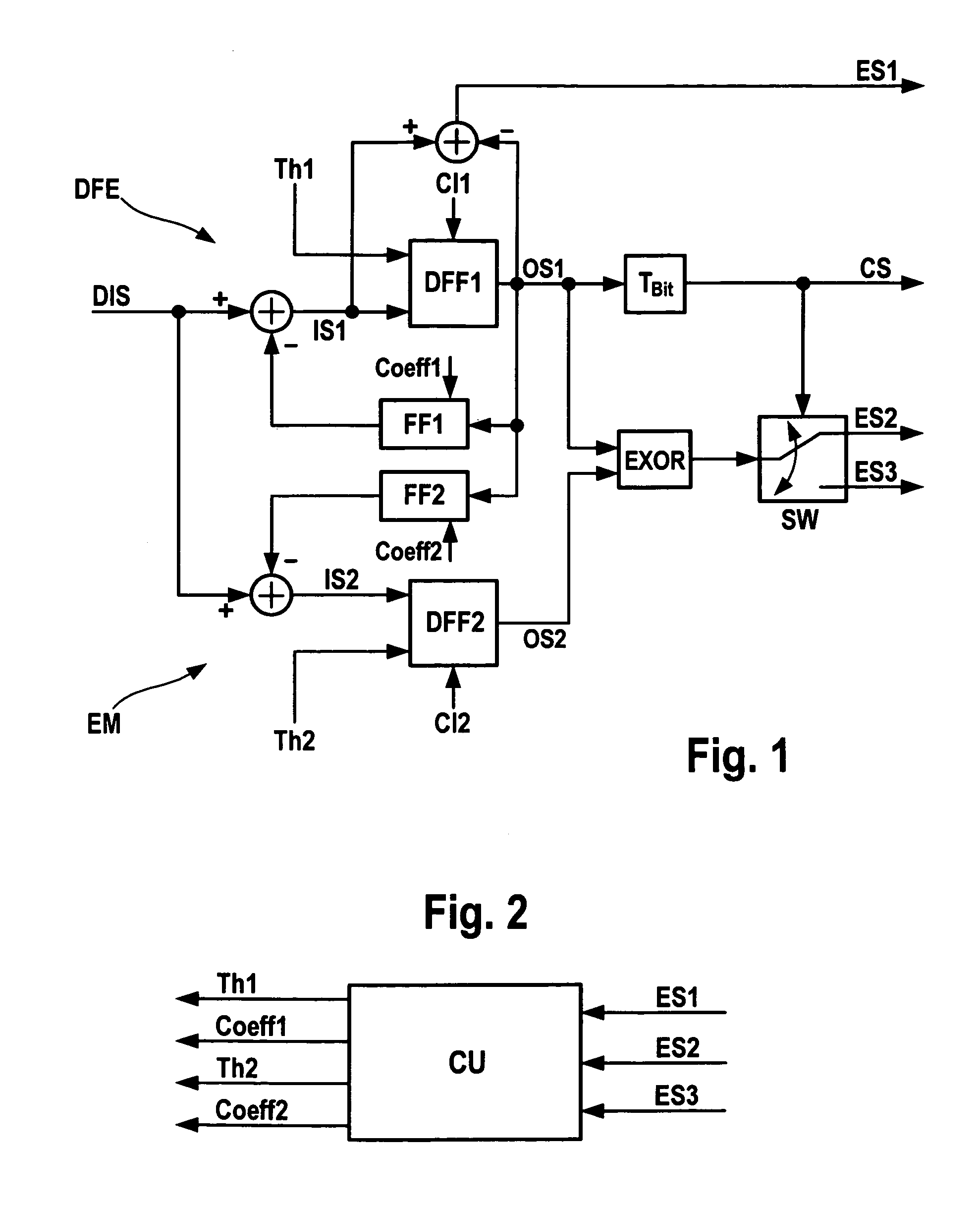
[0019]FIGS. 1 and 2 show parts of a receiver for an optical signal. In addition to the shown electrical circuits, the receiver comprises an opto-electrical converter that is connected to a fiber on which the optical signal is transmitted. Originally, the optical signal is generated as a binary signal. However, due to signal dispersion, the optical signal becomes distorted on its transmission along the fiber. The converter then receives the distorted optical signal and converts it into an electrical signal. The generated electrical signal is distorted, too, and is hereinafter called distorted input signal DIS.

[0020]According to FIG. 1, a first decision flip-flop DFF1 is provided that is part of a decision feedback equalizer DFE. The first decision flip-flop DFF1 may be adjusted by a first threshold signal Th1. As well, a first clock phase Cl1 is provided to the first decision flip-flop DFF1. The first decision flip-flop DFF1 generates a first output signal OS1 that is input to a firs...


PUM


Abstract

A receiver for an optical signal is described. The receiver comprises a decision feedback equalizer (DFE), wherein a distorted input signal (DIS) being derived from the optical signal, as well as a first threshold signal (Th1) and / or a first coefficient (Coeff1) are provided to the decision feedback equalizer (DFE), and wherein an error signal (ES1) is provided by the decision feedback equalizer (DFE). The receiver comprises a control unit (CU), wherein the error signal (ES1) is provided to the control unit (CU), and wherein the first threshold signal (Th1) and / or the first coefficient (Coeff1) are adapted by the control unit (CU). The receiver comprises an eye monitor (EM) for optimizing the adapted first threshold signal (Th1) and / or the adapted first coefficient (Coeff1), wherein the distorted input signal (DIS) is provided to the eye monitor (EM).

Description

[0001]The invention is based on a priority application EP 05291661.6 which is hereby incorporated by reference.BACKGROUND OF THE INVENTION[0002]The invention relates in general to optical communication systems and in particular to a receiver for an optical signal.[0003]It is known that signal dispersion, for example polarization mode dispersion, is one of a number of limiting criterion in connection with optical communication systems, in particular in connection with fiber optical transmission links. Successive digital pulses are smeared along the optical link so that they are no longer distinguishable as well-defined pulses at a receiver. Instead, the pulses overlap what leads to a distorted optical signal with so-called inter-symbol interferences.[0004]It is also known that a decision feedback equalizer can be used in the receiver to eliminate the inter-symbol interferences. For that purpose, the decision feedback equalizer may comprise a feedforward filter and a feedback filter c...

Claims


Application Information

Patent Timeline
Patent Type & Authority Patents(United States)
IPC IPC(8): H03H7/30H03H7/40H03K5/159H04B10/66
CPCH04B10/66H04L1/20H04L25/03057H04L2025/03388H04L2025/03726
Inventor FRANZ, BERND
Owner RPX CORP
Why Eureka
Try Eureka