
Method of operating a wood chipper and power transmission system for use therewith

a power transmission system and wood chipper technology, applied in the field of wood chippers, can solve the problems of not allowing automatic starting, stopping or reversing of the feed wheel, and affecting the operation of the wood chipper

Active Publication Date: 2010-02-09
ALAMO GROUP
View PDF6 Cites 5 Cited by
  • Summary
  • Abstract
  • Description
  • Claims
  • Application Information

AI Technical Summary

Benefits of technology

The present invention is a method and apparatus for controlling a wood chipper using an electric switch and an electronic control unit (ECU). The method involves sensing the position of the feed control bar and controlling the movement of the feed wheel and the operation of the engine based on the position of the feed control bar. The technical effect of this invention is to provide a more efficient and precise control of the wood chipper, allowing for better performance and efficiency in the cutting and processing of wood.

Problems solved by technology

This actuation is accomplished by linkages which are often fragile, hard to adjust and subject to wear and abuse.
In addition, these traditional systems do not allow for automatic starting, stopping or reversing of the feed wheels.
However, the wood chippers having these additions present a variety of poorly configured linkages and too many hydraulic valves and hoses.
However, said patent provides only for automatic reversal and subsequent automatic forward rotation of the feed wheel without the ability to maintain the feed wheel in a stopped or non-rotating state in response to an increased load on the cutting assembly or engine.
In addition, the known prior art fails to provide a control system which allows a variety of functions related to controlling the feed wheel and the engine of the wood chipper.

Method used


Image

  • Method of operating a wood chipper and power transmission system for use therewith
  • Method of operating a wood chipper and power transmission system for use therewith
  • Method of operating a wood chipper and power transmission system for use therewith

Examples


Embodiment Construction

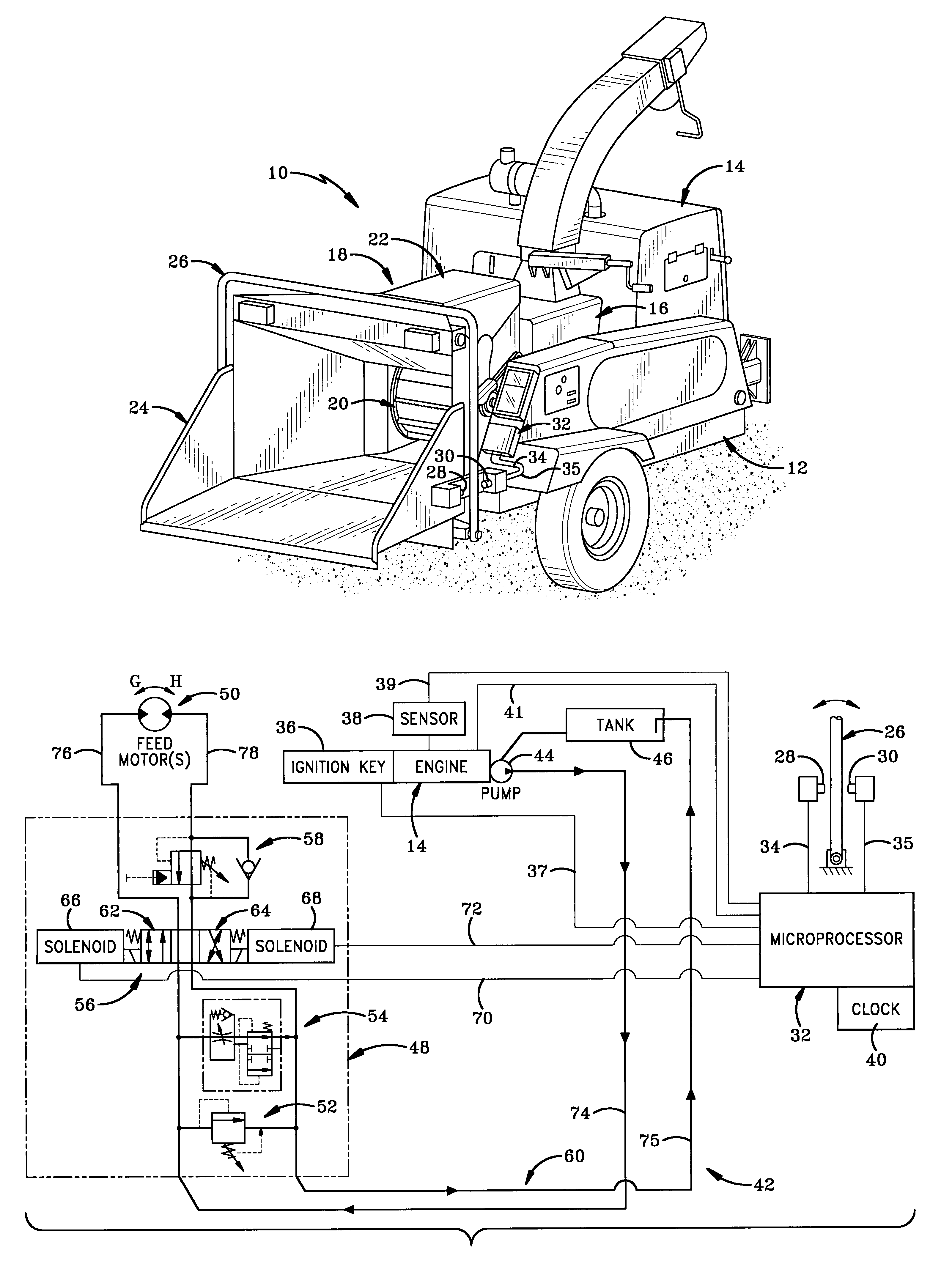
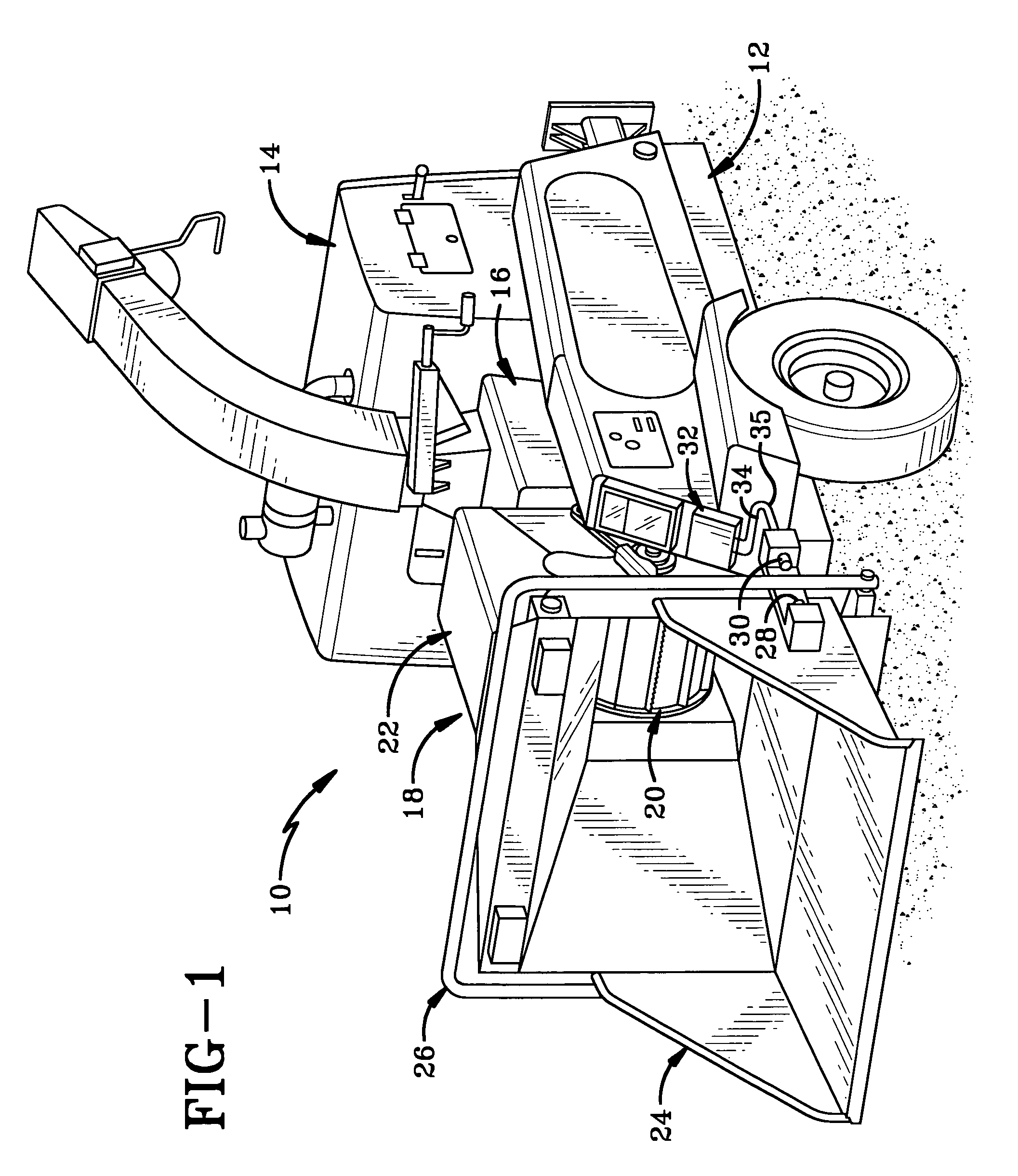
[0017]The wood chipper of the present invention is indicated generally at 10 in FIG. 1. Wood chipper 10 is configured with a control system providing several advantages. First, the control system prevents the starting of the wood chipper unless the feed mechanism for feeding materials into the chipper is in a neutral state. Second, the control system provides for the automatic stopping and / or reversing of the feed mechanism in response to an increased load upon the wood chipper. Third, the control system provides for a fuel-saving mechanism wherein the operational speed of the engine is decreased when the feed mechanism remains in a neutral state for a predetermined amount of time.

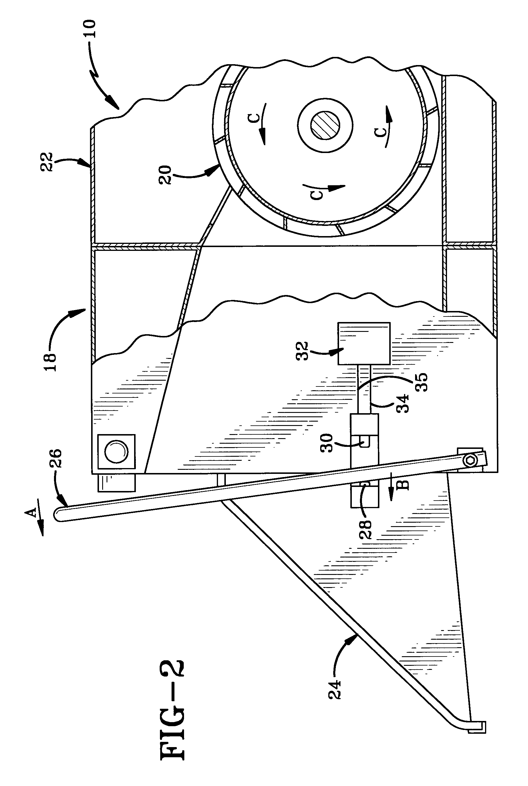
[0018]Wood chipper 10 is a wheeled vehicle having a frame 12 with an engine 14 mounted thereon. A cutting assembly 16 is mounted on frame 12 and is operatively connected to engine 14. A feed wheel assembly 18 is mounted on frame 12 adjacent cutting assembly 16 and opposite engine 14. Feed wheel assembly 18...


PUM


Abstract

A wood chipper includes a control system for controlling feed wheel rotation and engine operation to provide safety features and a fuel-saving mechanism. The control system allows the engine to start only when the feed wheel is in neutral; stops and / or reverses rotation of the feed wheel in response to an increased load on the engine; and dethrottles the engine if the feed wheel remains in neutral for a predetermined period of time. A pair of electric switches are activatable by the feed bar whereby an electronic control unit (ECU) can determine the position of the feed bar based on activation or non-activation of the switches and control the feed wheel and engine in light thereof. The ECU controls a pair of directional control valves via respective solenoids to control flow of hydraulic fluid to control rotation of a feed motor which drives the feed wheel.

Description

BACKGROUND OF THE INVENTION[0001]1. Technical Field[0002]The invention relates generally to wood chippers. More particularly, the invention relates to a control system for controlling the feed of material into the wood chipper and the operation of the engine of the wood chipper. Specifically, the invention relates to such a control system which includes an engine-starting safety mechanism, a fuel-saving mechanism and a mechanism for automatically stopping or reversing the feed mechanism in response to an increased load upon the engine.[0003]2. Background Information[0004]Typically, wood chippers include an engine for powering a chipper and a hydraulic system for rotating a feed wheel which feeds wood material and the like into the wood chipper where the material is cut by a cutting assembly housed within the chipper. Safety regulations require that wood chippers have a feed control bar which runs along the top and sides of the feed chute of the wood chipper so that operators may eas...

Claims


Application Information

Patent Timeline
Patent Type & Authority Patents(United States)
IPC IPC(8): B23Q15/00B23Q16/00
CPCB02C18/2283B02C25/00
Inventor CHAPMAN, BRUCE G.
Owner ALAMO GROUP
Learn More