Dual-chip integrated heat spreader assembly, packages containing same, and systems containing same

a heat spreader and integrated circuit chip technology, applied in the direction of semiconductor devices, semiconductor/solid-state device details, electrical devices, etc., can solve the problem that processors and other integrated circuit chips can generate significant hea

Inactive Publication Date: 2010-02-09
INTEL CORP
View PDF13 Cites 69 Cited by
  • Summary
  • Abstract
  • Description
  • Claims
  • Application Information

AI Technical Summary

Problems solved by technology

Processors and other integrated circuit chips can generate significant heat.

Method used


Image

  • Dual-chip integrated heat spreader assembly, packages containing same, and systems containing same
  • Dual-chip integrated heat spreader assembly, packages containing same, and systems containing same
  • Dual-chip integrated heat spreader assembly, packages containing same, and systems containing same

Examples


Embodiment Construction

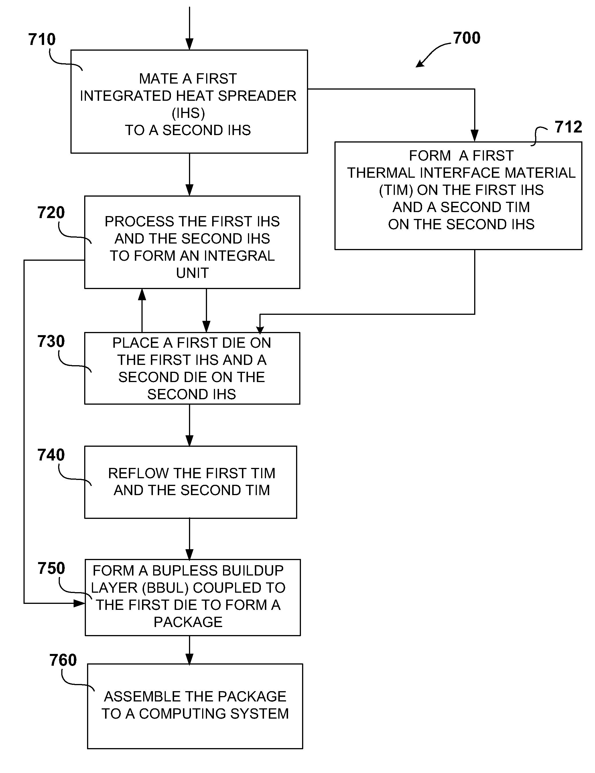
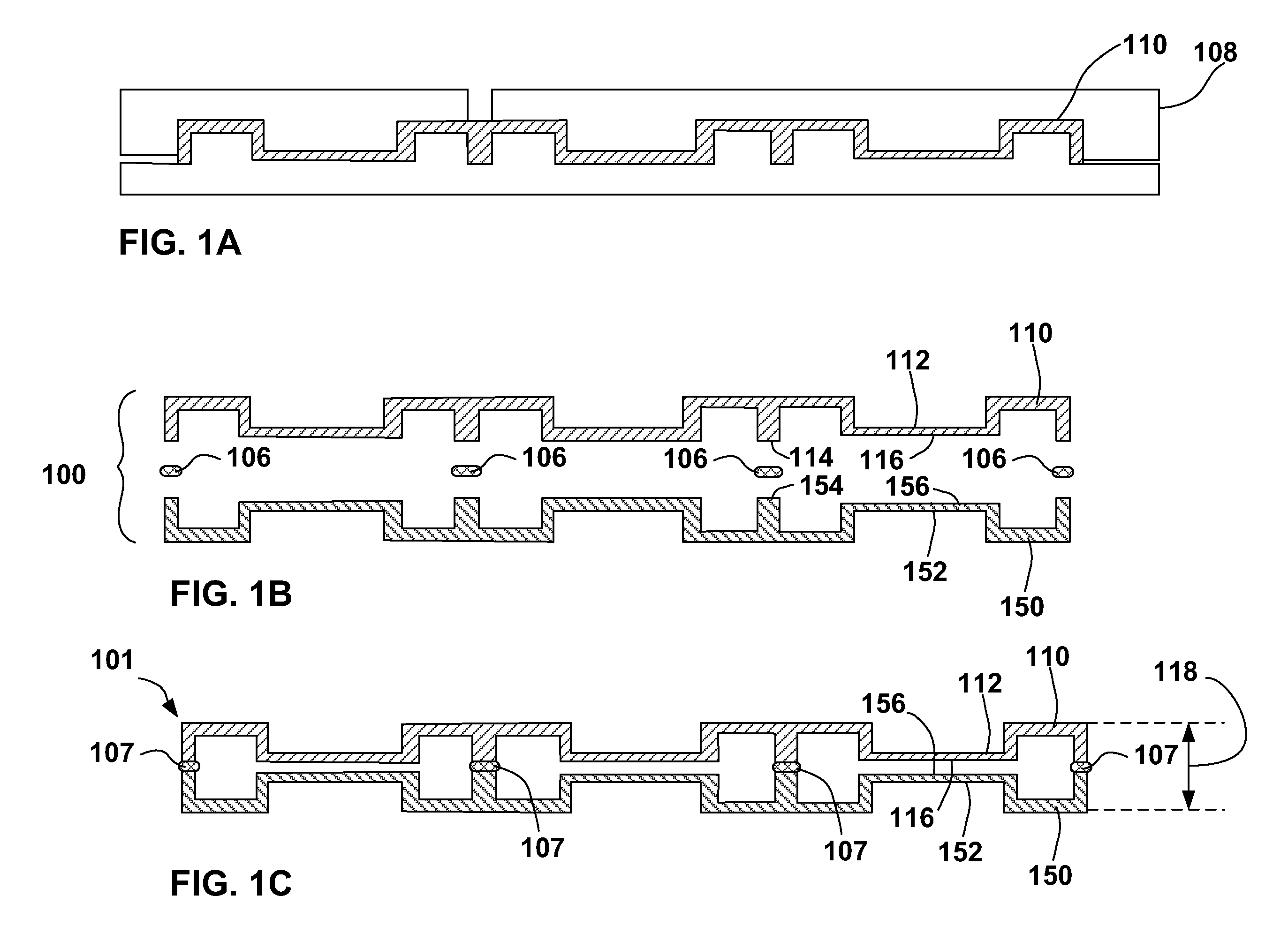
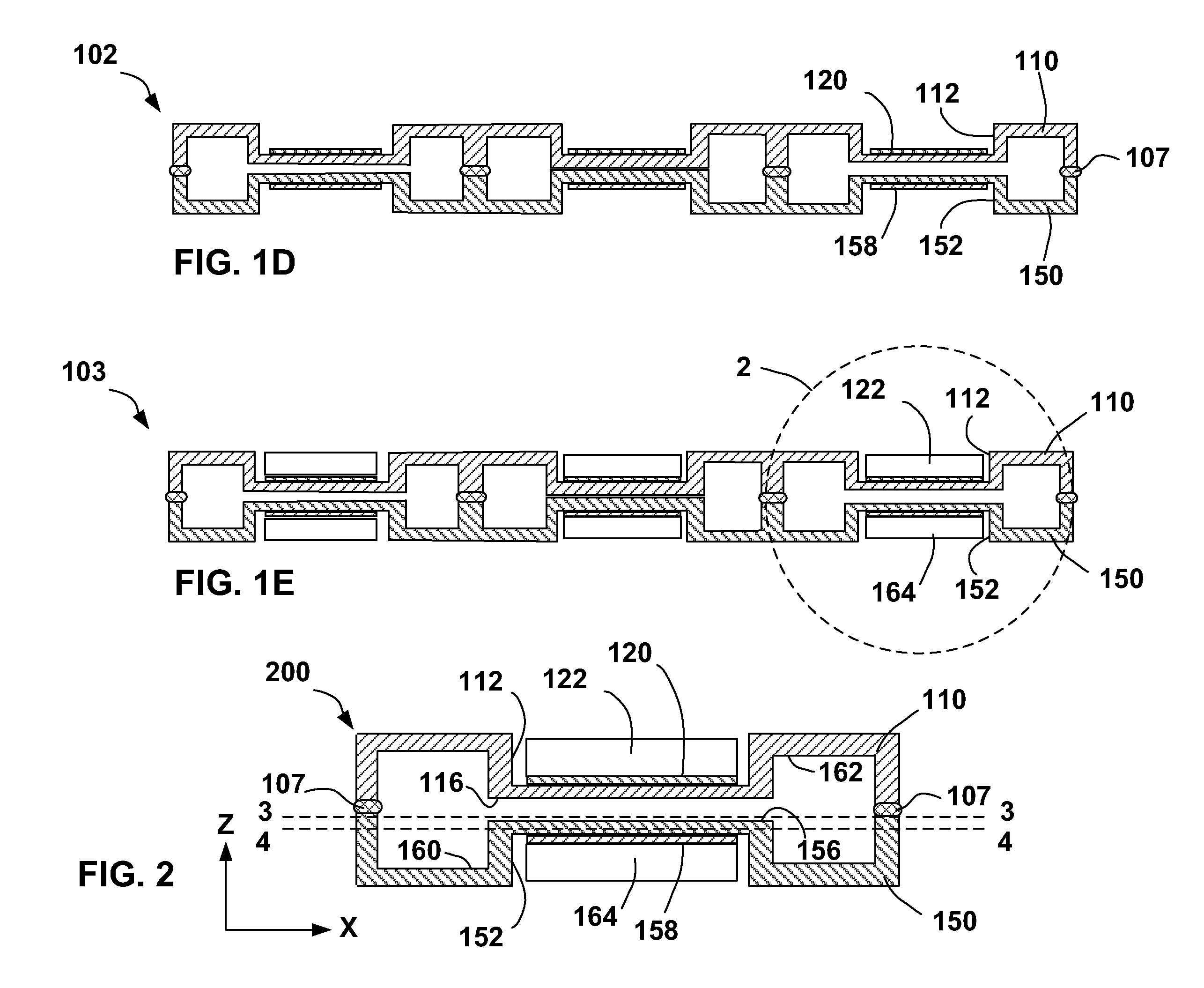
[0019]Embodiments in this disclosure relate to a process for forming a die in a heat spreader recess. Embodiments also relate to methods of assembling a bumpless build-up layer after forming a die in a heat spreader recess.

[0020]The following description includes terms, such as upper, lower, first, second, etc. that are used for descriptive purposes only and are not to be construed as limiting. The embodiments of an apparatus or article described herein can be manufactured, used, or shipped in a number of positions and orientations. The terms “die” and “chip” generally refer to the physical object that is the basic workpiece that is transformed by various process operations into the desired integrated circuit device. A die is usually singulated from a wafer and wafers may be made of semiconducting, non-semiconducting, or combinations of semiconducting and non-semiconducting materials. A board is typically a resin-impregnated fiberglass structure acting as a mounting substrate for th...


PUM


Abstract

A method includes mating a first heat spreader and a second heat spreader, such that the first heat spreader at a mating surface and second heat spreader at a mating surface become parallel and adjacent. The mated first heat spreader and second heat spreader have at least one convection channel disposed therebetween. A process includes placing a first die in a first die recess of the first heat spreader, and placing a second die on a second die site on the second heat spreader. The process includes reflowing thermal interface material between each die and respective heat spreader. A package is achieved by the method, with reduced thicknesses. The package can be coupled through a bumpless build-up layer. The package can be assembled into a computing system.

Description

TECHNICAL FIELD[0001]Embodiments relate generally to a dual-chip level integration of devices.TECHNICAL BACKGROUND[0002]Processors and other integrated circuit chips can generate significant heat. During miniaturization efforts, not only are circuits being crowded into smaller geometries, but multiple chips are also being crowded into smaller packages.BRIEF DESCRIPTION OF THE DRAWINGS[0003]In order to depict the manner in which the embodiments are obtained, a more particular description of embodiments briefly described above will be rendered by reference to exemplary embodiments that are illustrated in the appended drawings. Understanding that these drawings depict only typical embodiments that are not necessarily drawn to scale and are not therefore to be considered to be limiting of its scope, the embodiments will be described and explained with additional specificity and detail through the use of the accompanying drawings in which:[0004]FIG. 1A is a cross-section elevation that i...

Claims


Application Information

Patent Timeline
Patent Type & Authority Patents(United States)
IPC IPC(8): H01L21/00
CPCH01L23/473H01L24/24H01L24/82H01L24/97H01L25/0657H01L2224/24227H01L2224/97H01L2225/06524H01L2225/06575H01L2225/06589H01L2924/01029H01L2924/14H01L2924/1433H01L2924/15153H01L2924/15165H01L2224/82H01L2924/01005H01L2924/01006H01L2924/01033H01L2924/014H01L2224/32245H01L2224/73267H01L2224/92244H01L2224/04105
Inventor TANG, JIAMIAOLU, DAOQIANGHE, JIANGQIZENG, XIANG YIN
Owner INTEL CORP
Why Eureka
Try Eureka