Hydraulic elevation apparatus and method
a technology of hydraulic equipment and hydraulic lift, which is applied in the direction of earth-moving drilling and mining, loading/unloading, bulk conveyors, etc., can solve the problems of inefficient and relatively costly methods and devices used to lift rocks, insufficient space utilization, and insufficient efficiency of hoisting materials individually or by load in existing vertical shafts. , to achieve the effect of reducing the number of cylinders, and reducing the number of cylinder
- Summary
- Abstract
- Description
- Claims
- Application Information
AI Technical Summary
Benefits of technology
Problems solved by technology
Method used
Image
Examples
first embodiment
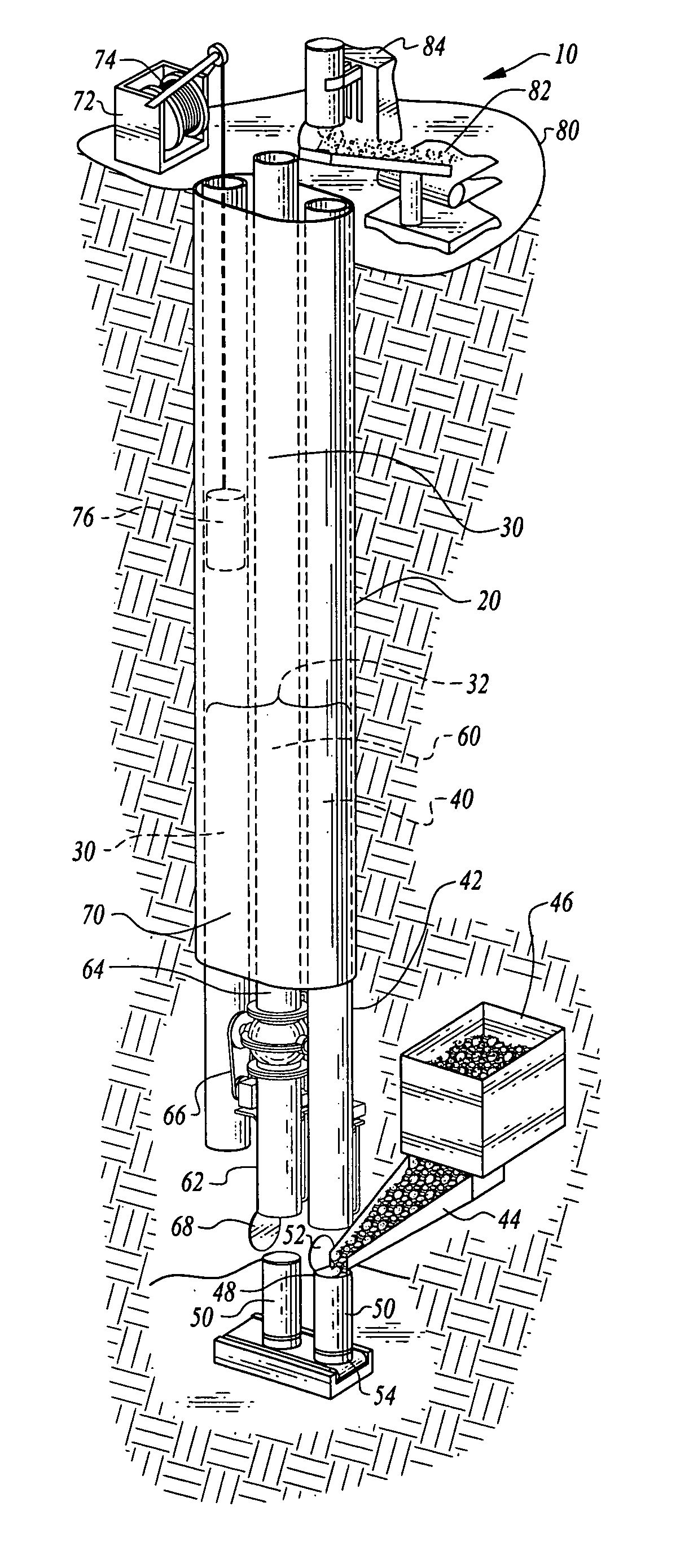
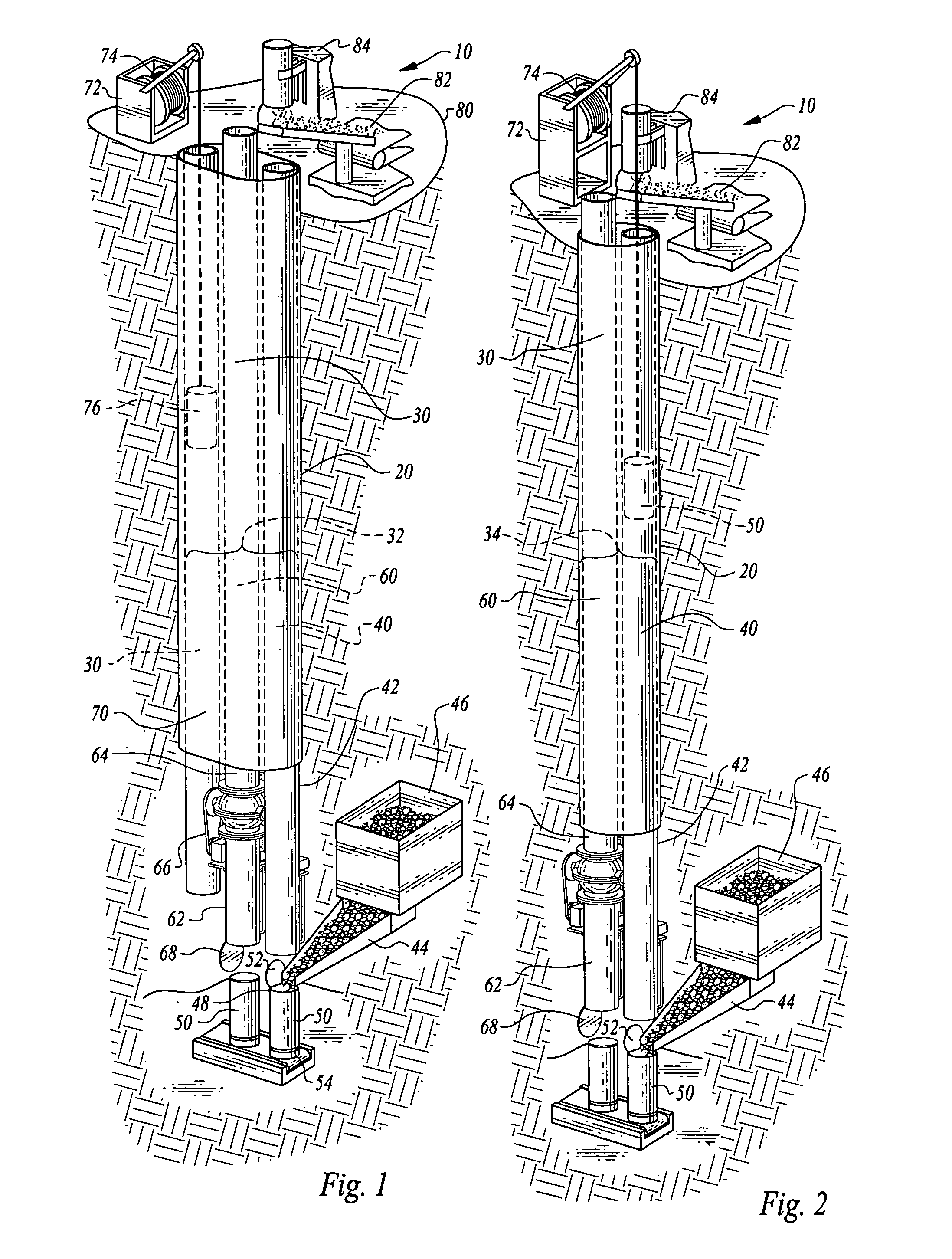
[0079]FIGS. 1 and 2 depict preferred embodiments of elevation apparatus (10) in a vertical lifting orientation. FIG. 1 shows elevation apparatus (10) employing a chamber framework (30) comprising a tripartite cavity structure (32) positioned within shaft elevation structure (20). Tripartite cavity structure (32) of chamber framework (30) includes a return chamber (40), a transport container (50), a delivery chamber (60), and an auxiliary hoist chamber (70). Auxiliary hoist chamber (70) may be optionally positioned laterally and adjacent to delivery chamber (60). A surface hoist (72) comprising a pulley mechanism (74) and an operatively attached transport container (76) is employed within auxiliary hoist chamber (70) as an optional lifting mechanism to transport objects within chamber framework (30).
second embodiment
[0080]FIG. 2 shows the elevation apparatus (10) employing a chamber framework (30) comprising a dual cavity structure (34) positioned within shaft elevation structure (20). Dual cavity structure (34) of chamber framework (30) includes a return chamber (40), a transport container (50), and a delivery chamber (60). As depicted in FIG. 2, transport container (50) may be lowered within return chamber (40) via a hoist, pulley, or similar such mechanism. Return chamber (40) includes a lower section (42), operatively positioned in relation to a transport channel (44). The outwardly extended top portion of transport channel (44) is connected to bin (46), which stores material to be elevated within chamber framework (30). Transport channel (44) is operatively positioned to engage transport container (50), which travels within return chamber (40) and delivery chamber (60) as described below.
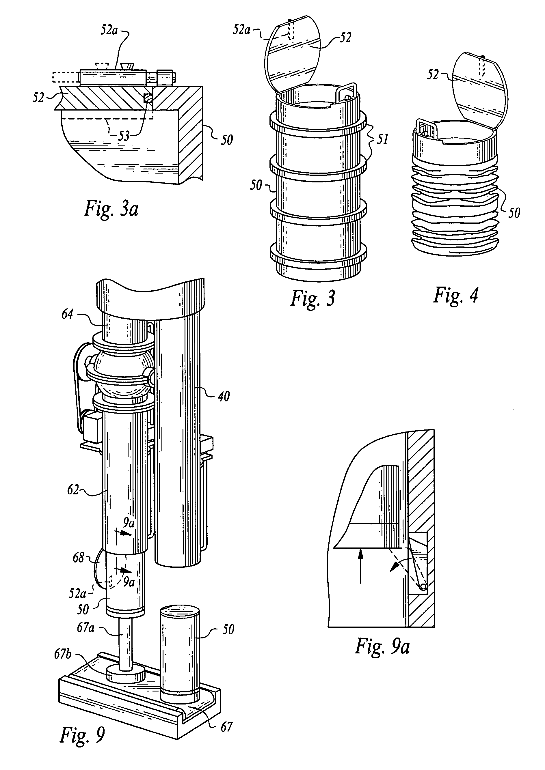
[0081]As shown in FIGS. 3-4, transport container (50) is constructed with a top end hatch (52) and a bo...
third embodiment
[0091]FIG. 14 shows elevation apparatus (10) of the present invention in an incline lifting orientation. Shaft elevation structure (20) is situated in a sloped orientation to facilitate transporting objects at an angle within chamber framework (30) on a graded incline, as opposed to in a vertical orientation. Chamber framework (30) includes a dual cavity structure (34) including return chamber (40a), delivery chamber (60), and transport container (50a) in operative communication with chamber framework (30). Return chamber (40a) includes a lower section (42) constructed and disposed to facilitate operative communication of transport container (50a) with transport channel (44) and bin (46), and additionally includes a laterally disposed ventilation channel (41), to permit air circulation within return chamber (40a) simultaneously with movement of transport container (50a) within return chamber (40a). In an alternative embodiment of the present invention (not shown), transport containe...
PUM
 Abstract
Description
Claims
Application Information
 - R&D
- Intellectual Property
- Life Sciences
- Materials
- Tech Scout
- Unparalleled Data Quality
- Higher Quality Content
- 60% Fewer Hallucinations
Browse by: Latest US Patents, China's latest patents, Technical Efficacy Thesaurus, Application Domain, Technology Topic, Popular Technical Reports.
© 2025 PatSnap. All rights reserved.Legal|Privacy policy|Modern Slavery Act Transparency Statement|Sitemap|About US| Contact US: help@patsnap.com


