
System and a method for manipulating a cassette used in storage by means of a transfer device

a transfer device and cassette technology, applied in the direction of lifting devices, loading/unloading, parkings, etc., can solve the problems of the rearmost wheel of the support on the bracket of the rack, the front edge of the support and the idler of the transfer device are not exactly at the same height, and the rearmost wheel of the support cannot be precisely positioned. , to achieve the effect of reducing the number of cassettes and/or support rolls, and reducing the number of friction

Active Publication Date: 2010-02-16
FASTEMS
View PDF28 Cites 31 Cited by
  • Summary
  • Abstract
  • Description
  • Claims
  • Application Information

AI Technical Summary

Benefits of technology

[0008]Another advantage of the invention is to keep the structures simple, wherein the number of the cassettes and / or support rolls can be minimized, but still allowing a way of transfer with little friction. In particular, it becomes easier to stop the stacker crane at the correct height, because the requirement of precision is significantly reduced, and the movements of lifting and lowering the stacker crane are even used to facilitate the transfer of the load into the stacker crane and back to the rack.
[0009]It becomes possible to manipulate even heavy loads, and the effect of the loading changes caused by them will not affect the capacity of the lift or transfer device to transfer the cassette or to keep the correct height level and position of the stacker crane. At the same time, the precision requirements for the installation of the rack system are reduced, as the transfer device does not need to be precisely positioned at a given height.
[0010]One particular embodiment of the cassette has the advantage that there is no need to provide the rack system with holes, stoppers, arresters or other equipment to lock the cassette in its position. Even though the rear end of the cassette is provided with an idler which is allowed to roll, the cassette cannot move from its position, because the cassette, supported by its front part, rests in the rack. The front part is also equipped with an idler, but this does not rest on a bracket.

Problems solved by technology

However, the problem is that the stacker crane and the base are not precisely at the same height, wherein the box hits the rolls of the stacker crane when the stacker crane is higher than the rack.
Also in this case, the transfer of the wheels from the bracket onto the transfer device is critical, and problems are caused by the collision of the wheels with the brackets of the transfer device or by their falling between the bracket of the rack and the transfer device.
If the base is equipped with wheels, problems include particularly the collision of the foremost wheel with the structures of the transfer device as well as the collision of its front edge with the idlers of the transfer device.
Another problem is the return of the rearmost wheel of the support onto the brackets of the rack.
The collision of the box with the structures of the stacker crane can be easily perceived from EP 0116126 A1 and it may be acceptable in the case of boxes with a light weight, but as the weight of the bases and the materials increase, the force effects caused by collisions are great, causing noise and damaging the structures, thereby increasing the need for repair and maintenance.
Also document EP 0379688 A1 requires precise positioning in the correct location, which may be even impossible if the cassettes are heavy, because the structures may yield, move or be displaced as well, due to the heavy loads.

Method used


Image

  • System and a method for manipulating a cassette used in storage by means of a transfer device
  • System and a method for manipulating a cassette used in storage by means of a transfer device
  • System and a method for manipulating a cassette used in storage by means of a transfer device

Examples


Embodiment Construction

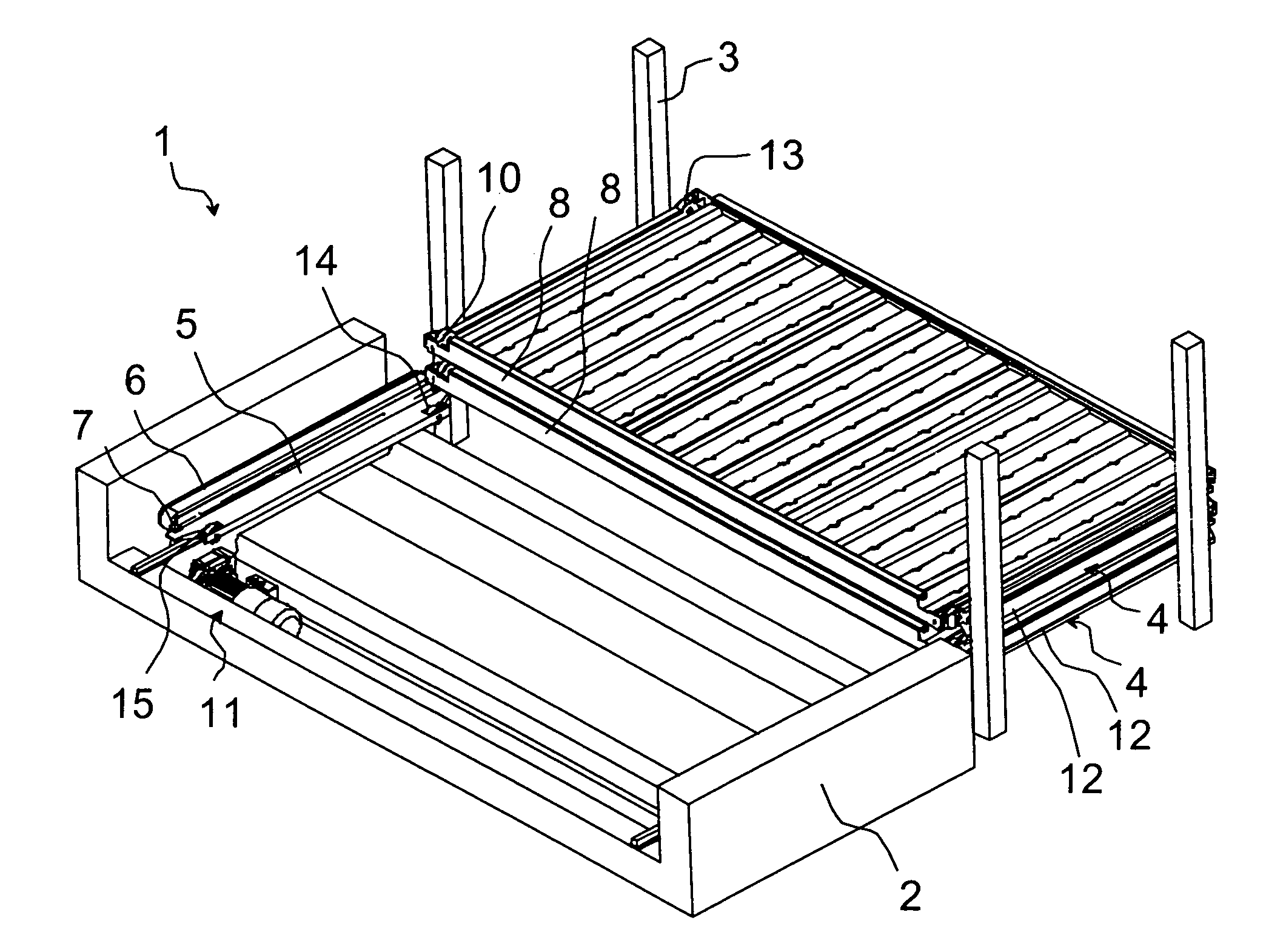
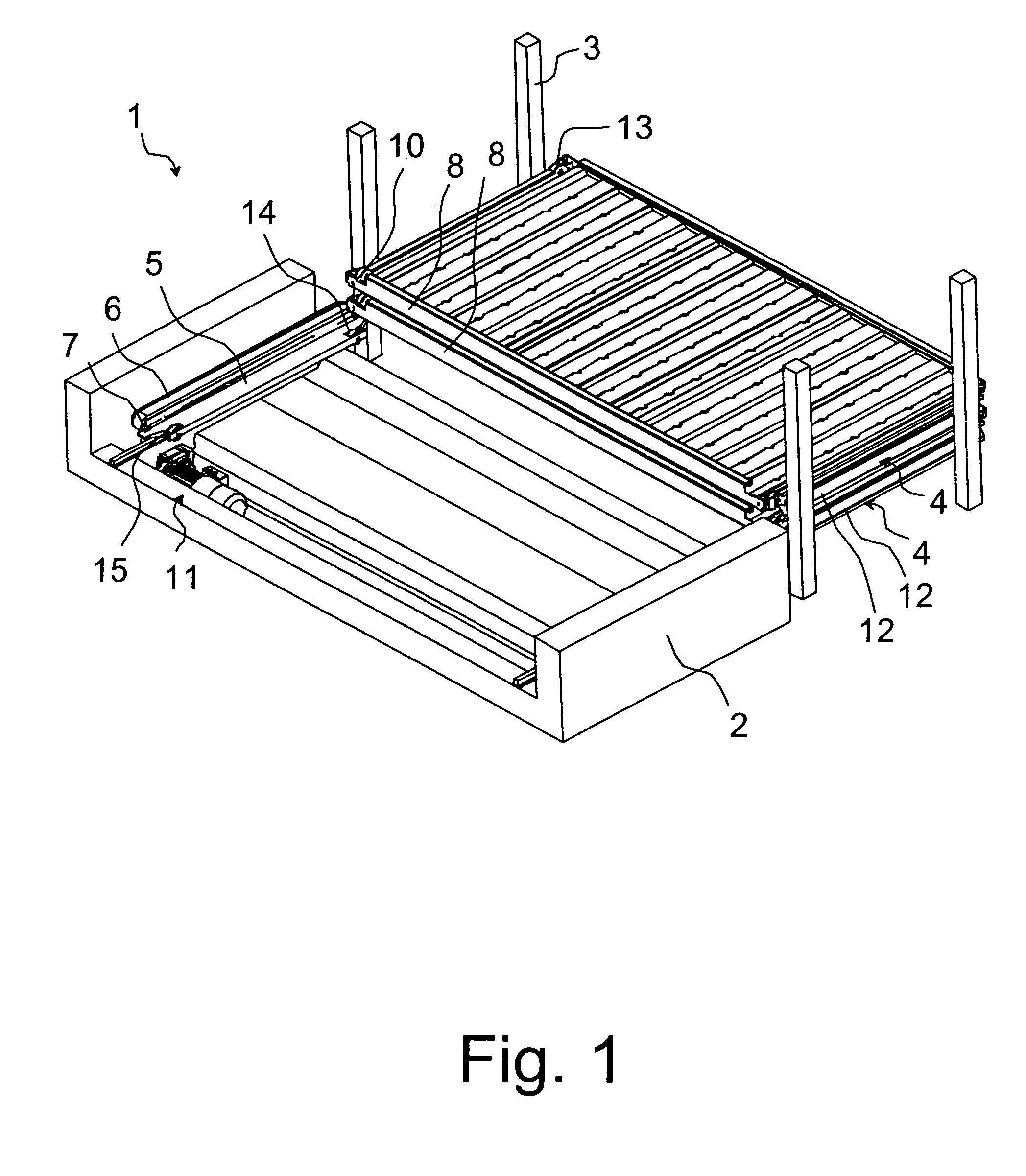
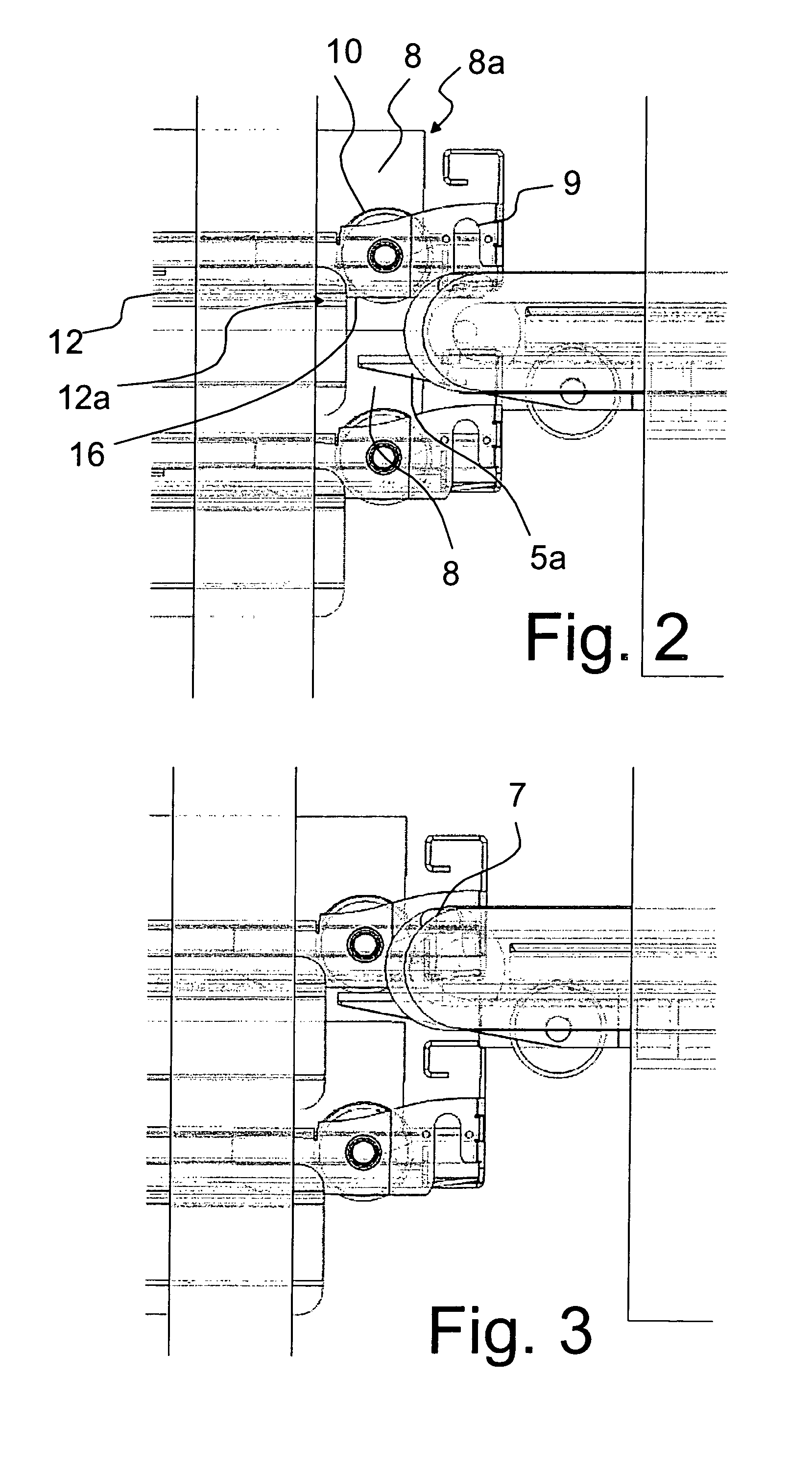
[0018]FIG. 1 shows the lifting carriage or the frame structure 2 of a transfer device 1, arranged to be lifted and lowered. In a particular embodiment of the invention, it is a stacker crane 1 with its lifting carriage 2. In another embodiment, the elevating structure is not the frame structure 2 but a pair of slides 5 which supports a cassette 8 and onto which the cassette is pulled. In the following description, an elevating and descending lifting carriage 2 will be used as an example. In FIG. 1, both the lifting carriage 2 of the transfer device 1 and two storage levels 4 of a rack 3 are illustrated as a simplified structure. In the case of the stacker crane 1, it is a stacker crane of prior art which moves in a way known as such either at one set of racks or in an aisle between two sets of racks. The structure of the set of racks 3 can be implemented and dimensioned in a variety of ways which are known as such from the design of warehouses. The aisles and the sets of racks are p...


PUM


Abstract

A method and a storage and manipulation system for manipulating and transferring cassettes used for storage. The system includes a rack for storing cassettes. The rack includes supports on which the cassette rests. A transfer device includes a slide, onto which the cassette can be transferred. The slide includes a lifting and lowering movement. The transfer device also includes grippers that grip the cassette and moving it onto or off the slide. The slide can be placed underneath the front part of the cassette and, by a lifting movement, elevate the front part of the cassette such that the cassette can be transferred along the support onto the slide. A rear part of the cassette is simultaneously supported by the support. The slide can also lower the front part of the cassette onto the support when the rear part of the cassette is transferred onto the support of the rack.

Description

BACKGROUND OF THE INVENTION[0001]It is known that, for example, automatic flexible manufacturing systems and automatic storage systems involve the feeding of materials, sheets and work pieces for machining, storing or other handling. The work pieces are typically placed on various bases, trays or pallets. Material sheets of various sizes can also be placed in various cassettes which are used as transport supports and in which the materials can also be stored.[0002]Typically, the system also comprises various automatic lift and transfer devices which transfer work pieces in the system, to be processed further or to be stored in a storage rack, and back. Lift and transfer devices include, for example, stacker cranes that handle cassettes, bases, trays, pallets or work pieces and comprise suitable devices, such as transfer forks, telescopic forks, lifting mechanisms, grippers, or the like, particularly for moving bases and cassettes to the stacker crane and back to the rack. Other lift...

Claims


Application Information

Patent Timeline
Patent Type & Authority Patents(United States)
IPC IPC(8): B65G1/00B65G1/04E04H6/24
CPCB65G1/0435
Inventor KANTOLA, JUHANARAPILA, TEROHALKOLA, TEPPORAEVAARA, VESAKORTESMAKI, JYRKI
Owner FASTEMS
Learn More