
Magnetic energy recovery switch having protective circuit

a technology of magnetic energy recovery switch and protective circuit, which is applied in the direction of emergency protective circuit arrangement for limiting excess voltage/current. it can solve the problems of high-speed breakage of load, semiconductor-type inverter power supply in recent years, and inability to withstand

Inactive Publication Date: 2011-10-25
MERSTECH
View PDF10 Cites 10 Cited by
  • Summary
  • Abstract
  • Description
  • Claims
  • Application Information

AI Technical Summary

Benefits of technology

"The present invention relates to a magnetic energy recovery switch that can protect against overvoltage and overcurrent in an electric power system. The switch has a protective circuit to prevent damage to the switches and the load caused by overcurrent or overvoltage. The switch can also limit the current and allow a continued operation without power breaking. The invention addresses the need for a continuous operation as far as possible without power breaking in case of an unexpected accident. The switch can be designed to be smaller and more cost-effective while still providing the necessary protection against overcurrent and overvoltage."

Problems solved by technology

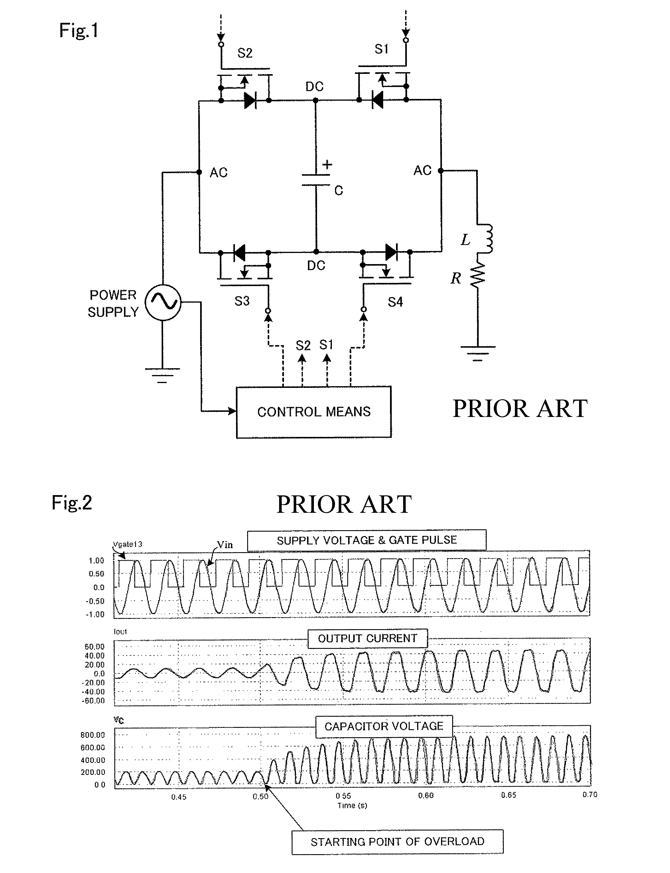
However, in an abnormality or a trouble of a load that causes an overcurrent, a measure taken thereagainst is a high-speed breaking of the load, as is exercised by a fuse or a high-speed mechanical switch.
A semiconductor-type inverter power supply in recent years, such as a fuel cell inverter, for example, cannot withstand, in many cases, a peak current which is almost ten times the excitation inrush current of a transformer.
Inverter power supplies, therefore, have various soft-start functions, which work if there is one load for one inverter power supply but may not work for late-started ones of a plurality of loads connected to one inverter power supply.

Method used


Image

  • Magnetic energy recovery switch having protective circuit
  • Magnetic energy recovery switch having protective circuit
  • Magnetic energy recovery switch having protective circuit

Examples


an embodiment

Simulation of an Embodiment

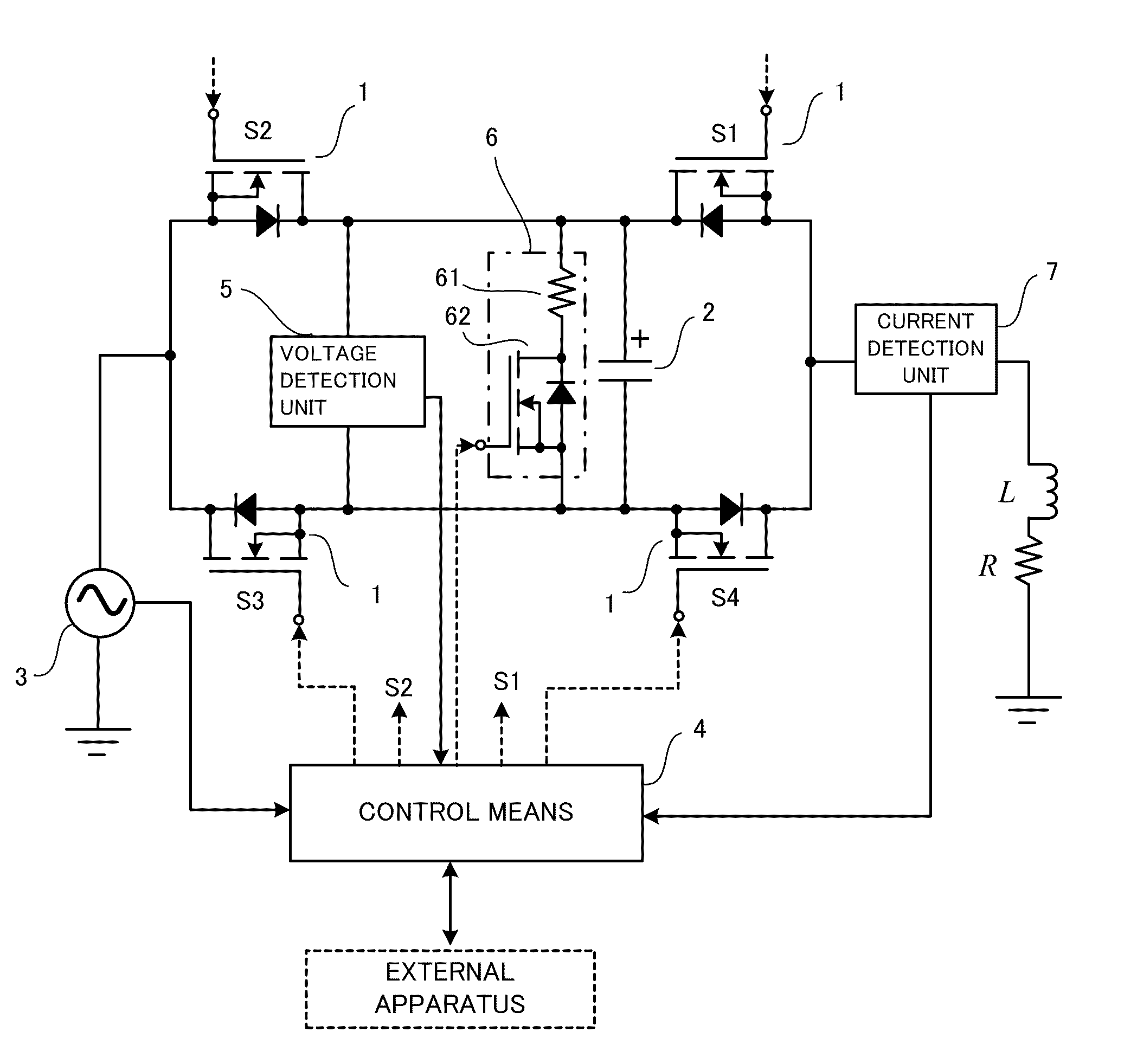
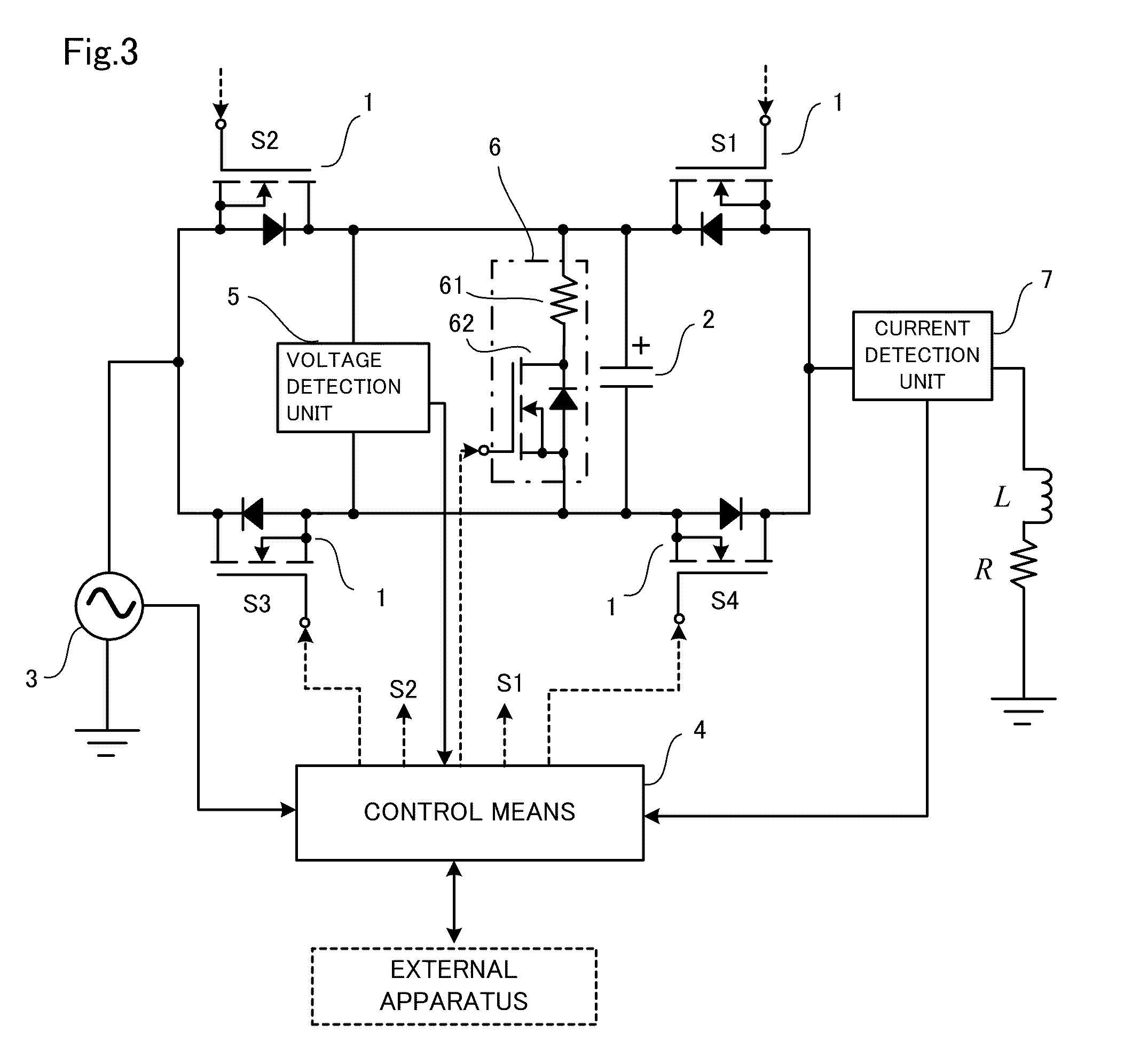
[0058]FIG. 8 shows a circuit block diagram for a simulation and FIG. 9 shows analyzed results thereof. The circuit consonants are as follows:

[0059]1. semiconductor switches: S1, S2, S3, S4 (Power MOSFETs; conducting loss is ignored.)

[0060]2. AC power supply: 50 Hz, AC 100V

[0061]3. load inductance L: 31.85 mH

[0062]4. load resistance R: 10Ω

[0063]5. load resistance at abnormal time R′: 2Ω

[0064]6. duration: 0.1 s

[0065]7. capacitor: 150 μF, overvoltage protection level (threshold value) 400V

[0066]A case in which a load resistance value is drastically changed after 0.5 seconds thereby causing a rapid increase in the current is simulated. As a result of the increase in the current, the capacitor now has an overvoltage and the discharge circuit gets in motion and the voltage is cut at 400V. When the overcurrent is detected by the current detection unit 7, the pulse width of the gate ON signals is reduced and after 0.1 seconds the current reduced, and, as a result,...


PUM


Abstract

In order to protect Magnetic Energy Recovery Switch (MERS) against an overvoltage and an overcurrent a voltage detection unit is provided for detecting the capacitor voltage of the MERS and control means is provided to control so as to turn ON the switch of the discharge circuit connected in parallel with the capacitor to make the capacitor discharge the electric charge thereof when the output of the voltage detection unit exceeds a predetermined value. Moreover, a current detection unit is interposed between the AC power supply and the load for detecting the current flowing to the load, and the current limiting is carried out by making the duty ratio of the ON / OFF of the pulse of the gate control signals of the MERS switches smaller than 0.5, when the output of the current detection unit exceeds a predetermined value.

Description

TECHNICAL FIELD[0001]The present invention relates to a magnetic energy recovery switch connected between an AC power supply and a load and having a protective circuit for protection of reverse-conductive type semiconductor switches constituting the magnetic energy recovery switch against overvoltage and for protection of semiconductor switches and a load against overcurrent.BACKGROUND ART[0002]Nowadays electric power energy systems are critically important social infrastructure which cannot be stopped even for a moment. However, in an abnormality or a trouble of a load that causes an overcurrent, a measure taken thereagainst is a high-speed breaking of the load, as is exercised by a fuse or a high-speed mechanical switch. Nevertheless, there has been a demand for a highly functional switch, so called a controller or a current limiter, which is capable of limiting only the overcurrent and allowing a continued operation without the complete stop of the load, as well as a system recov...

Claims


Application Information

Patent Timeline
Patent Type & Authority Patents(United States)
IPC IPC(8): H02H3/08
CPCH02M5/293H02M7/217H02J3/1814Y02E40/18H02M2003/1555H02M1/32H02M3/1555Y02E40/10
Inventor SHIMADA, RYUICHI
Owner MERSTECH
Learn More