Method and system for egr control

a technology of egr and control method, which is applied in the direction of electric control, combustion air/fuel air treatment, machines/engines, etc., can solve the problems of unacceptable long delay to reach high torque, unsatisfactory dilution of high egr, and inability to deliver egr (0% egr) , to achieve desirable combustion stability of the engine, reduce throttling losses, and improve vehicle emissions and fuel economy

Active Publication Date: 2015-07-09
FORD GLOBAL TECH LLC
View PDF3 Cites 15 Cited by
  • Summary
  • Abstract
  • Description
  • Claims
  • Application Information

AI Technical Summary

Benefits of technology

[0003]Exhaust gas recirculation (EGR) systems divert a portion of the exhaust gases back to the intake to cool combustion temperatures and reduce throttling losses, thus improving vehicle emissions and fuel economy. In turbocharged engines, an EGR system may include a cooled low-pressure EGR (LP-EGR) circuit wherein exhaust gases are diverted after the gases pass through the turbine of the turbocharger and injected before the compressor upon passage through an EGR cooler. Additionally, the EGR system may include a cooled high-pressure EGR (HP-EGR) circuit wherein exhaust gases are diverted before the gases pass through the turbine of the turbocharger and injected downstream of the compressor upon passage through an EGR cooler. The amount of EGR (HP-EGR and / or LP-EGR) routed through the EGR system is measured and adjusted based on engine speed and load during engine operation to maintain desirable combustion stability of the engine while providing emissions and fuel economy benefits.

Problems solved by technology

In addition, at very low engine loads and / or engine idle conditions, no EGR (0% EGR) may be delivered.
However the inventors herein have identified potential issues with EGR systems.
As an example, when high rates of EGR are present and low rates of EGR are requested (such as during selected “full” tip-ins), the delay to reach high torque may be unacceptably long.
This may be, at least in part, due to the long transport delay in EGR evacuating the intake system as the exhaust gases have to clear from the intake manifold before a full charge of pure air reaches the combustion chamber to produce maximum possible torque.
To mitigate the delay in producing the maximum torque, the maximum level of EGR is reduced under steady state conditions, increasing knock, inefficient use of spark retard or combustion mixture enrichment may be required degrading fuel economy, and offsetting the fuel economy benefits of the prior EGR usage.
As another example, when low rates of EGR are present and high rates of EGR are requested (such as during selected partial tip-ins), the delay to reach high EGR dilution may be unacceptably long.
This may be, at least in part, due to the long transport delay in EGR filling the intake system as the exhaust gases have to travel though the turbocharger compressor, high-pressure air induction plumbing, charge air cooler, and intake manifold before reaching the combustion chamber.
The delay in EGR entering the combustion chamber can also lead to combustion instability, and knock.
To mitigate the knock, inefficient use of spark retard or combustion mixture enrichment may be required degrading fuel economy, and offsetting the fuel economy benefits of the prior EGR usage.
The abnormal combustion events can also erode drive cycle fuel efficiency and potentially damage the engine.
As a further example, when high rates of EGR are present and low rates of EGR are requested (such as during selected tip-outs), the delay in EGR purging from the air intake system can lead to the presence of residual EGR dilution at low load conditions.
The presence of increased intake dilution at low loads can increase combustion instability issues and the propensity for engine misfires.
While the flat schedule of Styles may reduce the likelihood of high EGR amounts at lower engine loads, the schedule may also limit the fuel economy benefits of EGR.
For example, the flat EGR schedule may result in LP-EGR being provided at some low load points where no fuel economy benefits from EGR are achieved.
In some cases, there may even be a fuel penalty associated with the delivery of LP-EGR at the low load point.
As another example, the lower EGR at the lower load points may limit the peak EGR rates achievable during subsequent higher load engine operation.
The delayed purging of EGR requiring EGR in the engine intake system at low engine loads can also render the intake compressor susceptible to corrosion and condensation.
Furthermore, increased condensation may occur at the charge air cooler of a boosted engine system due to the flow of EGR through the cooler.
The increased condensation may necessitate additional counter-condensation measures which further reduce engine efficiency and fuel economy.

Method used


Image

  • Method and system for egr control
  • Method and system for egr control
  • Method and system for egr control

Examples


first embodiment

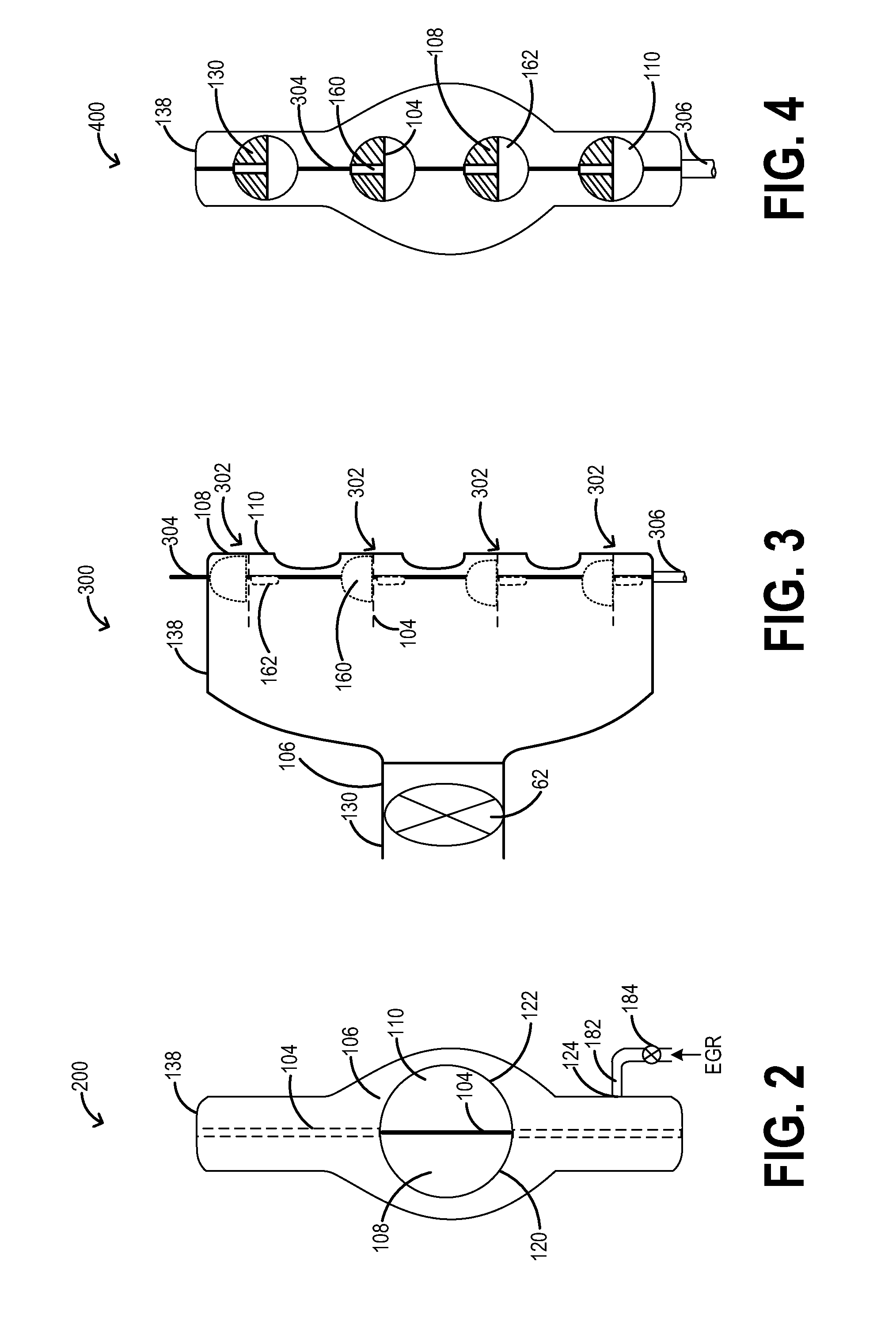
[0040]Now turning to FIGS. 2-4, various views of the divided intake plenum is shown. Specifically, a first (left hand side) view 200 of the divided intake plenum is shown looking into the plenum from the intake throttle. A second top view 300 of the divided intake plenum is shown looking into the different plenum portions from a top of the intake plenum. Finally, a third (right hand side) view 400 of the divided intake plenum is shown looking into the plenum from the intake ports of the cylinders. In the embodiment depicted at FIGS. 2-4, the first and second set of throttle valves are arranged in a perpendicular arrangement on a common shaft so as to allow for use of a common actuator. As such, components introduced earlier in FIG. 1 are numbered similarly and not reintroduced.

[0041]FIG. 2 shows a first (left hand side) view 200 looking in towards the intake plenum 138 from the intake throttle, at inlet 106 of the intake plenum. That is, the view depicts the intake plenum when looke...

second embodiment

[0046]Now turning to FIGS. 5-7, various views of the divided intake plenum is shown. Specifically, a first (left hand side) view 500 of the divided intake plenum is shown looking into the plenum from the intake throttle. A second top view 600 of the divided intake plenum is shown looking into the different plenum portions from a top of the intake plenum. Finally, a third (right hand side) view 700 of the divided intake plenum is shown looking into the plenum from the intake ports of the cylinders. In the embodiment depicted at FIGS. 5-7, the first and second set of throttle valves are arranged on distinct shafts so as to allow for independent control. As such, components introduced earlier in FIGS. 1-4 are numbered similarly and not reintroduced.

[0047]As discussed at FIG. 2, FIG. 5 shows a first (left hand side) view 500 looking in towards the intake plenum 138 at an inlet end, from the intake throttle at inlet 106 of the intake plenum. As such, the view of the intake plenums at the...


PUM


Abstract

Methods and systems are provided for improving control of high dilution EGR. An intake plenum is divided so that fresh intake air and EGR can be delivered to engine cylinders via dedicated plenum portions. Distinct sets of throttles are provided in the cylinder intake ports coupled the different plenum portions so that a ratio of intake air flow and EGR flow to the engine cylinders can be rapidly adjusted in response to sudden changes (e.g., increase or decrease) in EGR demand.

Description

CROSS REFERENCE TO RELATED APPLICATIONS[0001]The present application claims priority to U.S. Provisional Patent Application No. 61 / 924,188, “METHOD AND SYSTEM FOR EGR CONTROL,” filed on Jan. 6, 2014, the entire contents of which are hereby incorporated by reference for all purposes.FIELD[0002]The present application relates to methods and systems for improving dilution control in an internal combustion engine.BACKGROUND AND SUMMARY[0003]Exhaust gas recirculation (EGR) systems divert a portion of the exhaust gases back to the intake to cool combustion temperatures and reduce throttling losses, thus improving vehicle emissions and fuel economy. In turbocharged engines, an EGR system may include a cooled low-pressure EGR (LP-EGR) circuit wherein exhaust gases are diverted after the gases pass through the turbine of the turbocharger and injected before the compressor upon passage through an EGR cooler. Additionally, the EGR system may include a cooled high-pressure EGR (HP-EGR) circuit ...

Claims


Application Information

Patent Timeline
Patent Type & Authority Applications(United States)
IPC IPC(8): F02D41/00F02M25/07
CPCF02D41/005F02M25/0771F02M25/0706F02D41/0065F02D2041/0017F02M26/44Y02T10/40F02M35/10222
Inventor MARTIN, DOUGLAS RAYMONDGATES, FREEMAN CARTER
Owner FORD GLOBAL TECH LLC
Why Eureka
Try Eureka