Human-powered driving mechanism

a technology of driving mechanism and human power, which is applied in the direction of rider propulsion, vehicle components, gearing, etc., can solve the problems of reducing the speed increasing ratio below a certain level, the speed changing mechanism does not improve energy conversion efficiency, and the driving mechanism of a human-powered vehicle has not changed at all in principle, so as to achieve the effect of efficient conversion of human power into driving for

Inactive Publication Date: 2003-04-01
ODA NORIYUKI
View PDF18 Cites 16 Cited by
  • Summary
  • Abstract
  • Description
  • Claims
  • Application Information

AI Technical Summary

Benefits of technology

is to solve the problems in the above described prior technologies, so that it becomes possible to provide a driving mechanism which is capable of efficiently converting human power into driving force, and therefore, is most suitable for

Problems solved by technology

However, the driving mechanism for a human-powered vehicle has not changed at all in principle.
In principle, a speed changing mechanism does not improve energy conversion efficiency, regardless of its configuration.
However, reducing the speed increasing ratio below a certain level is meaningless.
That is, as the speed increasing ratio is reduced in order to keep the bicycle running, the rider must pedal faster to rotate the driving axle faster in reverse proportion to the decrease in the speed increasing ratio, which in turn causes the rider to reach his or her limit in physical capacity, and also increases the friction and/or vibrations for which the bearings and chain of the driving mechanism are responsible.
Eventually, it becomes impossible for the rider to keep the bicycle balanced to continue riding.
Thus, it is obvious that there is a limit in the improvement in slope climbing performance.
Actually, however, the ankle joints, knee joints, and hip joints, are limited in their ranges of movement, and therefore, the force applied to the pedal always acts downward in the virtually vertical direction regardless of rotational angle of the crank.
Thus, as far as a single rotational cycle of the crank is concerned, this structural arrangement for a human-powered vehicle driving mechanism has not increased power output in practical terms.
Thus, as far as the entirety of a single pedaling cycle is concerned, increase in power output cann

Method used


Image

  • Human-powered driving mechanism
  • Human-powered driving mechanism
  • Human-powered driving mechanism

Examples


first embodiment

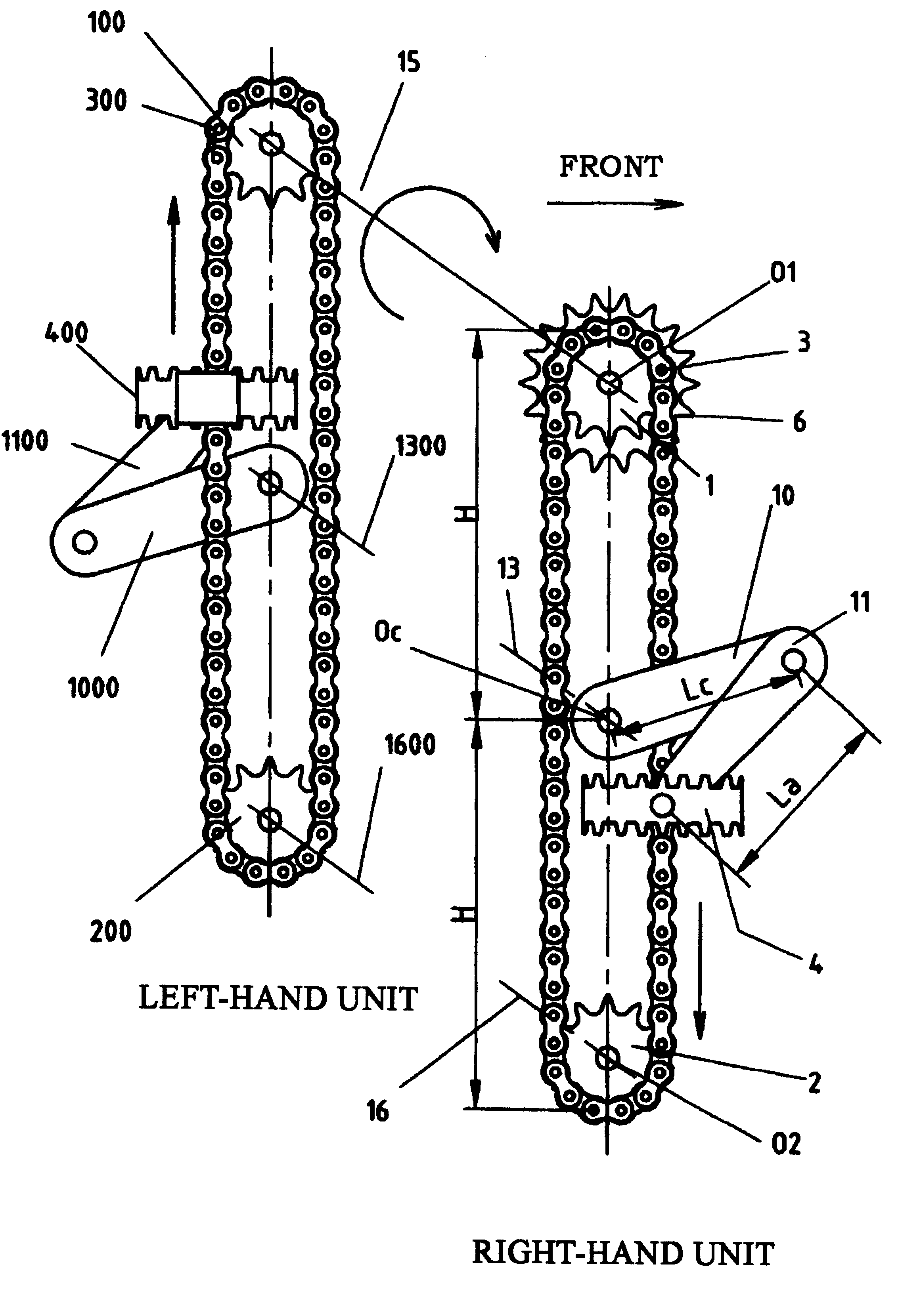
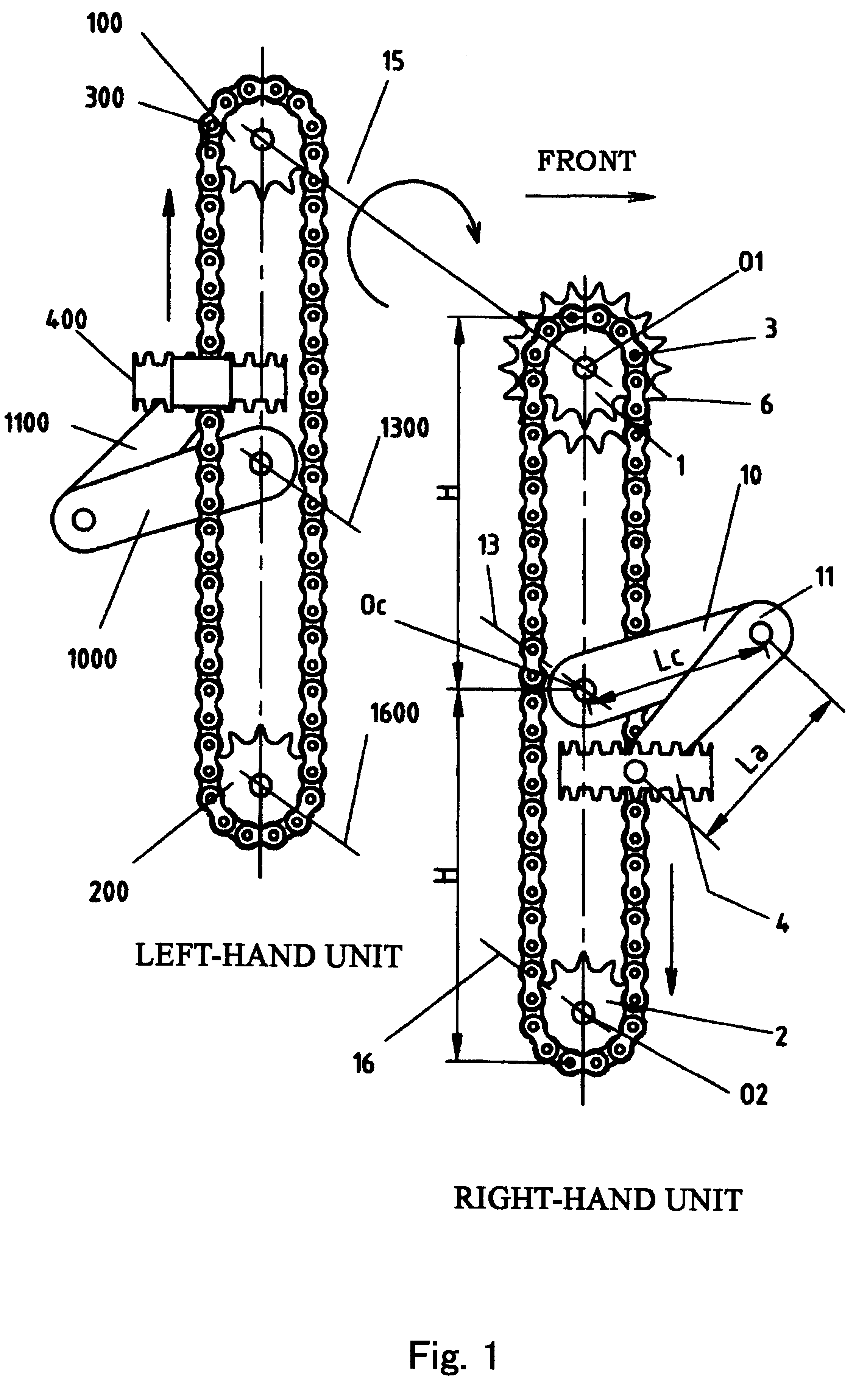
FIG. 1 shows a general arrangement of the human powered drive mechanism according to the present invention which is applied to a bicycle. Left and right human powered drive units are disposed parallel to each other. A line connecting the centers of a rotatable member and a rotatable supporting member extends vertically. Referring to FIG. 1, a human powered drive unit at a front side of the sheet of the drawing, that is, the right side unit of the rider is called "right-hand unit" (also referred to as a "first human powered drive unit"), and the other is called "left-hand unit" (also referred to as a "second human powered drive unit"), the parts of the right-hand unit are assigned with double-digit reference numerals, and the parts of the left-hand unit are assigned with the like numerals with "00" added. Left and right machine elements which need not be discriminated, such as bearings, nuts and the like are given the same reference numerals. FIGS. 2 to 9 illustrate the human powered...

third embodiment

When the third embodiment is applied to a bicycle, the power input is approx 1.18 times that of a conventional bicycle, on the assumptions that crank radius of the conventional bicycle is R; that average moving speeds of the pedals of the conventional bicycle and the bicycle of this example are the same; that in the linear range of the endless driving member at the power phase, the rotational force is kept at the same value as that at a crank angle of 90.degree. given in FIG. 13; that in the linear range of the endless driving member at the recovery phase, the rotational force is kept at the same value as that at a crank angle of 270.degree. given in FIG. 13; in the circular range of the endless driving member, the rotational force is equal to that of the corresponding crank angle given in FIG. 13.

In the physical meaning, the work is the product of the force acting on a point and the displacement of the point in the direction of the force, and therefore, if the displacement is zero,...

fourth embodiment

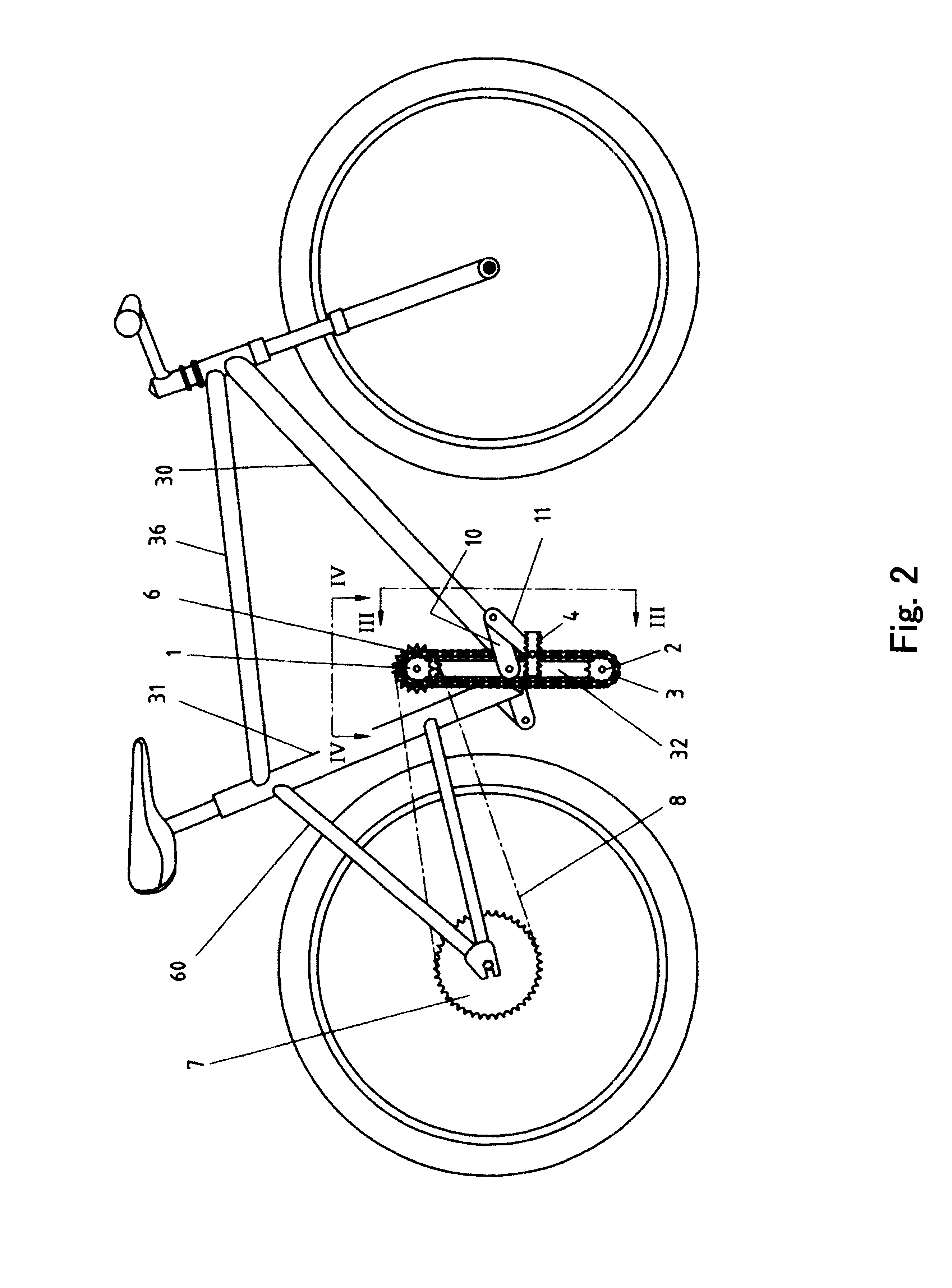
FIG. 14 is a side view of a human powered drive mechanism according to the present invention which is applied to a bicycle. FIG. 15 is a side view in which the left and right human powered drive mechanisms are removed. FIG. 16 is a side view a chain ring 6 and a transmission chain 8 are further removed. FIG. 17 is a partially sectional view in which parts of a bracket, a down tube and a seat tube are cut along a vertical plane including the center line of the bicycle. FIG. 18 illustrates details of a portion H of FIG. 17. FIG. 19 is a sectional view taken along a G--G of FIG. 16. FIG. 20 illustrates details of I portion of FIG. 17. FIG. 21 is an enlarged view of L portion of FIG. 18. FIG. 22 is a view as seen in a direction J in FIG. 18. FIG. 23 is a view as seen in the direction M in FIG. 16.

In FIGS. 14 to 19, the down tube 30 and the seat tube 31 are bifurcated at lower portions into right-hand member 30a and left-hand member 30b and into right-hand member 31a and left-hand member...


PUM


Abstract

A human powered drive units each including a pair of a rotatable member having a sprocket and a supporting member having a sprocket, which are arranged up and down, and including a chain extended around the rotatable member and the supporting member, are disposed at left and right sides, respectively. The left and right rotatable members 1, 100 are fixed on a driving shaft 15. A chain ring 6 on which the load is applied is mounted on the driving shaft between upper rotatable member 1 and rotatable member 100. In each of the units, constraining means including a free crank (10 for the right-hand unit, and 1000 for the left-hand unit) and arm (11 for the right-hand unit, and 1100 for the left-hand unit), is provided so as to maintain perpendicularity of a shaft of the pedal relative to the plane in which the chain moves. By the rider kicking the pedal along the closed orbit including a linear orbit portion, the force transmitted to the pedal from the foot of the rider is efficiently converted to a rotational force in a longer period of time, thus increasing the power input.

Description

The present invention primarily relates to a driving mechanism for a human-powered vehicle such as a bicycle, a wheelchair, a boat, or a human-powered airplane, or a human-powered machine comparable to a human-powered vehicle, for example, a muscle training machine.The driving mechanism for a bicycle and the driving mechanism for a leisure recreational pedal boat are identical in principle. Both driving mechanisms comprise a rotational axle, two cranks, or the left and right cranks, and a pair of pedals. More specifically, the two cranks are rendered different in rotational phase by 180.degree., with one end of each crank being fixed to the rotational axle at a right angle. The other end of each crank is provided with a shaft, which is anchored to the crank at a right angle, and around which a pedal is rotationally fitted. Torque is generated as an operator steps on the pedal, and this torque is used to rotate the propelling means, such as a wheel, a propeller, or the like, of a hum...

Claims


Application Information

Patent Timeline
IPC IPC(8): B62M1/04B62M1/20B62M1/00B62M1/02B62M3/00B62M3/06B62M1/36B62M1/24F16H7/00
CPCB62M1/20B62M3/06B62M1/28B62M1/24
Inventor ODA, NORIYUKI
Owner ODA NORIYUKI
Why Eureka
Try Eureka