Rod milling method and device

A rod mill and rod mill technology, applied in grain processing and other directions, can solve the problems of low overflow discharge output, low overall efficiency, and difficult load adjustment, and achieve the effects of easy operation, improved efficiency, and easy shutdown.

Inactive Publication Date: 2014-09-03
江苏东发重工科技有限公司
View PDF8 Cites 9 Cited by
  • Summary
  • Abstract
  • Description
  • Claims
  • Application Information

AI Technical Summary

Problems solved by technology

[0011] Although the structure of the existing rod mill is relatively simple, and the manufacturing parts are relatively few; the overflow discharge is the mainstream method; but the output of the overflow discharge is relatively low, the load adjustment is not easy, and the coarse running is serious at low load , needs to be operated at a high filling rate, so the overall efficiency is not high, and it also brings the disadvantage of relatively high cost. When the machine is shut down, there will be serious slurry overflow and waste slurry discharge.

Method used


Image

  • Rod milling method and device
  • Rod milling method and device
  • Rod milling method and device

Examples


Embodiment Construction

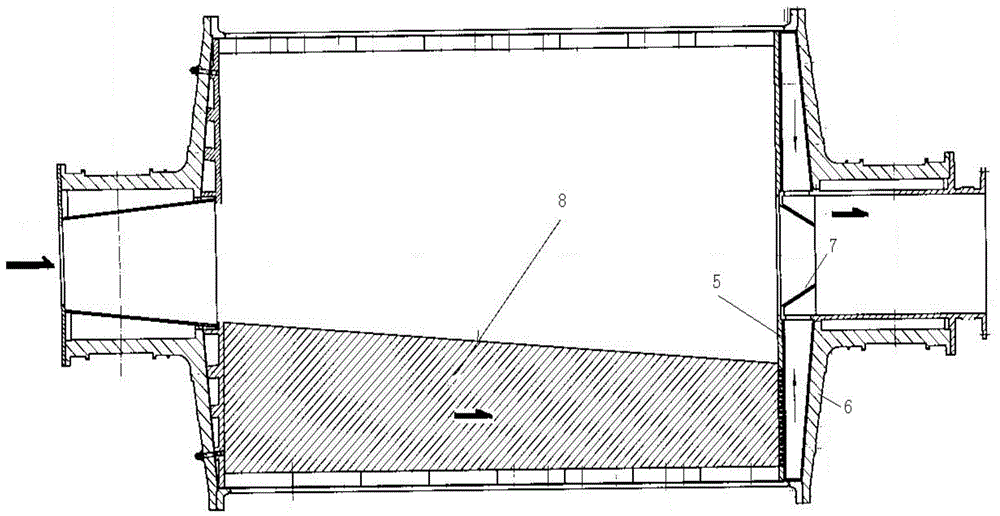
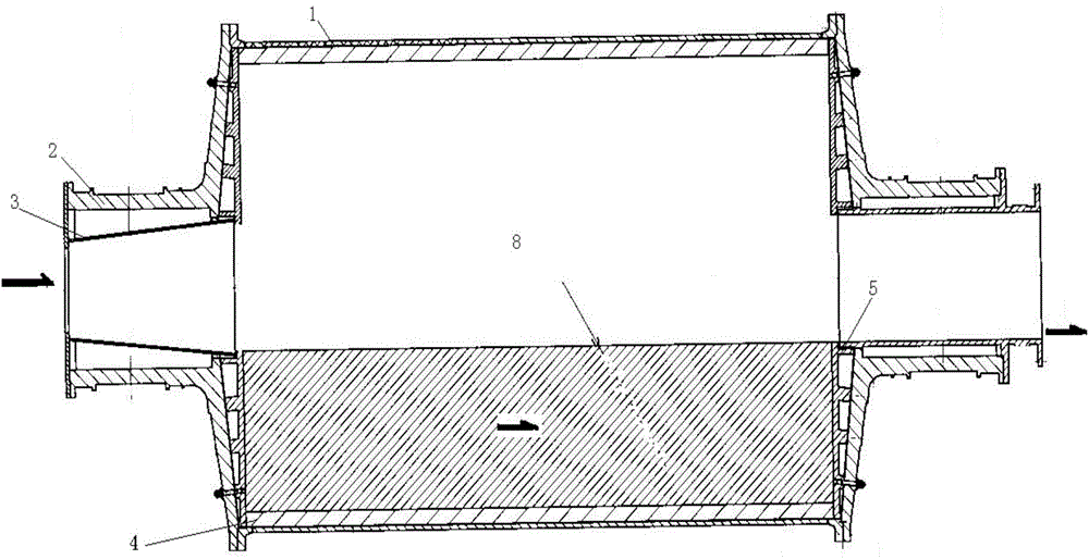
[0026] The rotary part, the rotary part is a cylinder 1 rolled and welded by steel plate, the two ends are respectively connected with the hollow shafts of the inlet and outlet with bolts, and are supported horizontally on the two main bearing bushes. The hollow shaft 2 is equipped with a feeding screw cylinder or other feeding cylinders 3 . The rotary part is rotated by the pinion gear through the large ring gear at one end of the fixed cylinder with the help of a reducer and a motor. A liner 4 is provided inside the cylinder, which not only protects the cylinder but also brings the steel rod to a suitable height to improve the efficiency of rod milling. In order to prevent dust and water leakage from the bolt holes of the liner, the bolts of the liner should be wrapped with a sealing device close to the outer wall of the cylinder. The barrel is equipped with a manhole door, which is used for repairing and replacing the internal parts of the whole body by unloading the grind...


PUM


Abstract

The invention discloses a rod milling method. Two ends of a rod milling barrel are respectively connected with a hollow feeding shaft and a hollow discharge shaft by using bolts, and horizontally supported on two main shaft bushings; a lining plate is arranged inside the barrel body; a plurality of milling rods of which the lengths are a little shorter than the length of the barrel are arranged inside the barrel and mill together with materials when rotating inside the barrel; a plurality of holes are distributed in the surface of a discharge end cover of a rod mill; a cavity formed by a barrel end cover or a plate with the same shape is arranged between the discharge sides of the discharge end cover; the sizing agent at the discharge end of the rod milling barrel is discharged out from the holes in the discharge end cover of the rod mill; the discharged sizing agent is taken to the upper part of the hollow shafts of the barrel by the rotating cavity, and is forcibly discharged.

Description

technical field [0001] The invention relates to a new method and device for rod milling. Background technique [0002] The rod mill is named after the grinding body loaded in the cylinder is a steel rod (or alloy material). The existing method of rod mill is mainly the discharge method is wet overflow, and the rod mill generally adopts wet overflow type. , can be used as a primary open circuit grinding, widely used in primary grinding of artificial stone sand, mineral processing plants, chemical plants, and electric power departments. It is also excellent for the preparation of coal water slurry and coal powder. The rod mill is mainly considered to have more uniform particle size and higher output; the fineness of the output can be adjusted. [0003] The rod mill is driven by the motor through the reducer and the surrounding large gears or the low-speed synchronous motor directly through the surrounding large gears to drive the cylinder to rotate. The barrel is filled wit...

Claims


Application Information

Patent Timeline
Patent Type & Authority Applications(China)
IPC IPC(8): B02C17/10B02C17/18
Inventor 钟小明姜丽琴张杰
Owner 江苏东发重工科技有限公司
Why Eureka
Try Eureka