Gas burner

a burner and gas technology, applied in the direction of burners, burner materials, combustion types, etc., can solve problems such as general instability, and achieve the effects of improving the useability of the cooktop, reducing the risk of clogging, and improving the control of clogging

Inactive Publication Date: 2010-02-16
DESIGNGASPARTS
View PDF25 Cites 28 Cited by
  • Summary
  • Abstract
  • Description
  • Claims
  • Application Information

AI Technical Summary

Benefits of technology

[0003]Gas burners generally come in different sizes. The size generally will define the maximum BTU output of the gas burner. Depending upon the design of the flame rings of the specific burners, gas burners generally have a maximum output of approximately 15,000 BTU's (British Thermal Units), and have a diameter of approximately 4 inches (102 mm). The maximum BTU output is also governed by the flame density of the burner ring, or the ring that has the holes for the flame. The current state of the art in gas burners has a low intensity (low BTU output) gas burner that is regulated only by the amount of fuel / air mixture that is allowed through the flame ring. There may be a low BTU flame ring, but generally it provides a BTU output greater than 1000 B, and is generally unstable due to the low pressure of the gas-air mixture. The present invention uses a separate secondary flame ring that is centrally located within the burner assembly and is not part of the main burner assembly. The secondary flame ring is much smaller than the main flame ring and produces a maximum of 850 BTU's but also has extremely fine control, allowing the user to be very precise in the use of the flame, preventing the burning of delicate foods. The fine control of the secondary flame ring also allows for much lower BTU output, which will prevent burning of cooked foods that are being kept warm. A burner cover is placed over the main and secondary flame rings to more evenly distribute the heat. The burner cover may have a transparent heat resistant insert that allows the cook to verify whether the flames have been extinguished or are still ignited.
[0004]The burner is mounted on top of an appliance and does not use the air within the appliance. This internal air is used for the range or oven. By not using the internal air of the oven or range, the air pressure spikes caused by a user shutting the oven door is prevented, thereby preventing the extinguishing of the flame on the burners.
[0006]It is another object of the invention to provide a gas burner that has a high BTU output (>18,000 BTU's) at a smaller diameter (100 mm or—4 inches), creating more useable space on the cooktop.
[0007]It is a further object of the invention to provide the user with a gas burner that has a much greater range of BTU output and with finer control of the BTU output.
[0008]Another object of the invention is to provide the user with a gas burner that does not use the air that is internal to the gas oven / range, which will eliminate air spikes caused by closing the oven and ultimately extinguish the main or secondary flames.
[0009]A further object of the invention is to provide the user with a gas burner that has a burner cap that contains a heat resistant transparent portion or translucent colored portion, that allows the cook to see the flame of the low intensity or secondary burner, which will alert the cook that the burner is in use.

Problems solved by technology

There may be a low BTU flame ring, but generally it provides a BTU output greater than 1000 B, and is generally unstable due to the low pressure of the gas-air mixture.

Method used


Image

  • Gas burner
  • Gas burner
  • Gas burner

Examples


Embodiment Construction

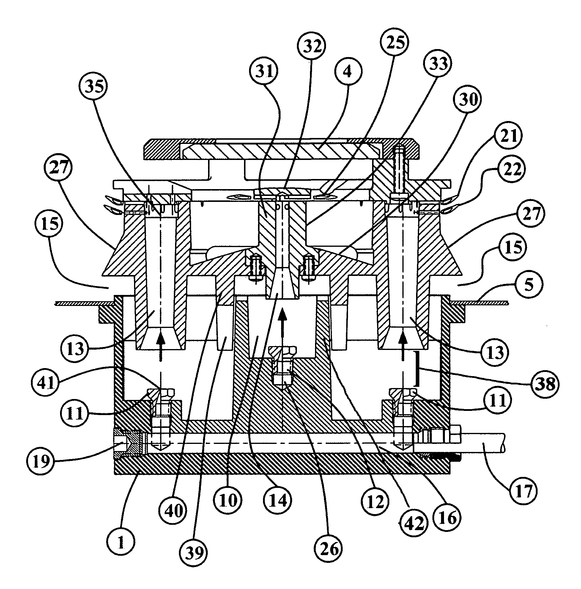
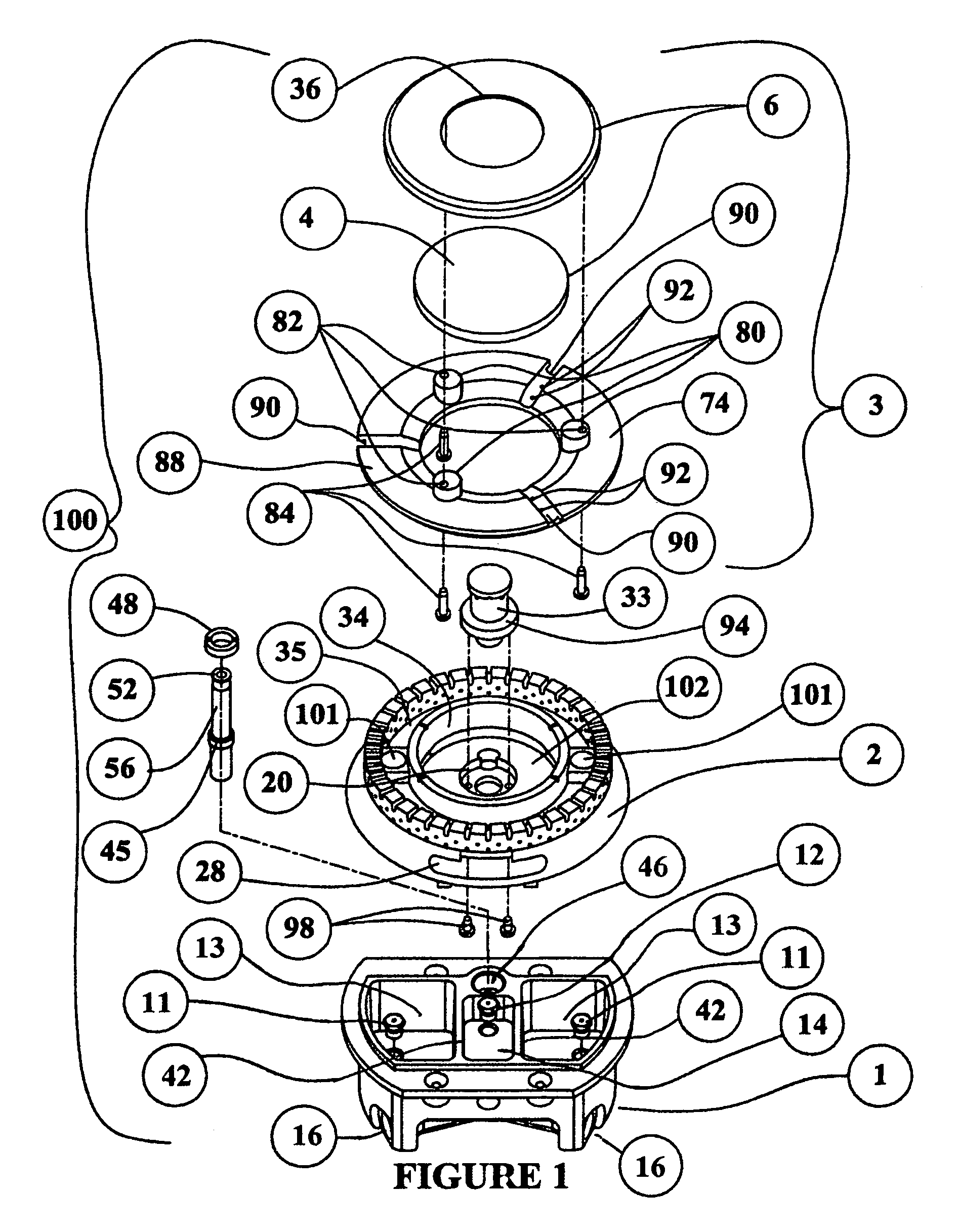
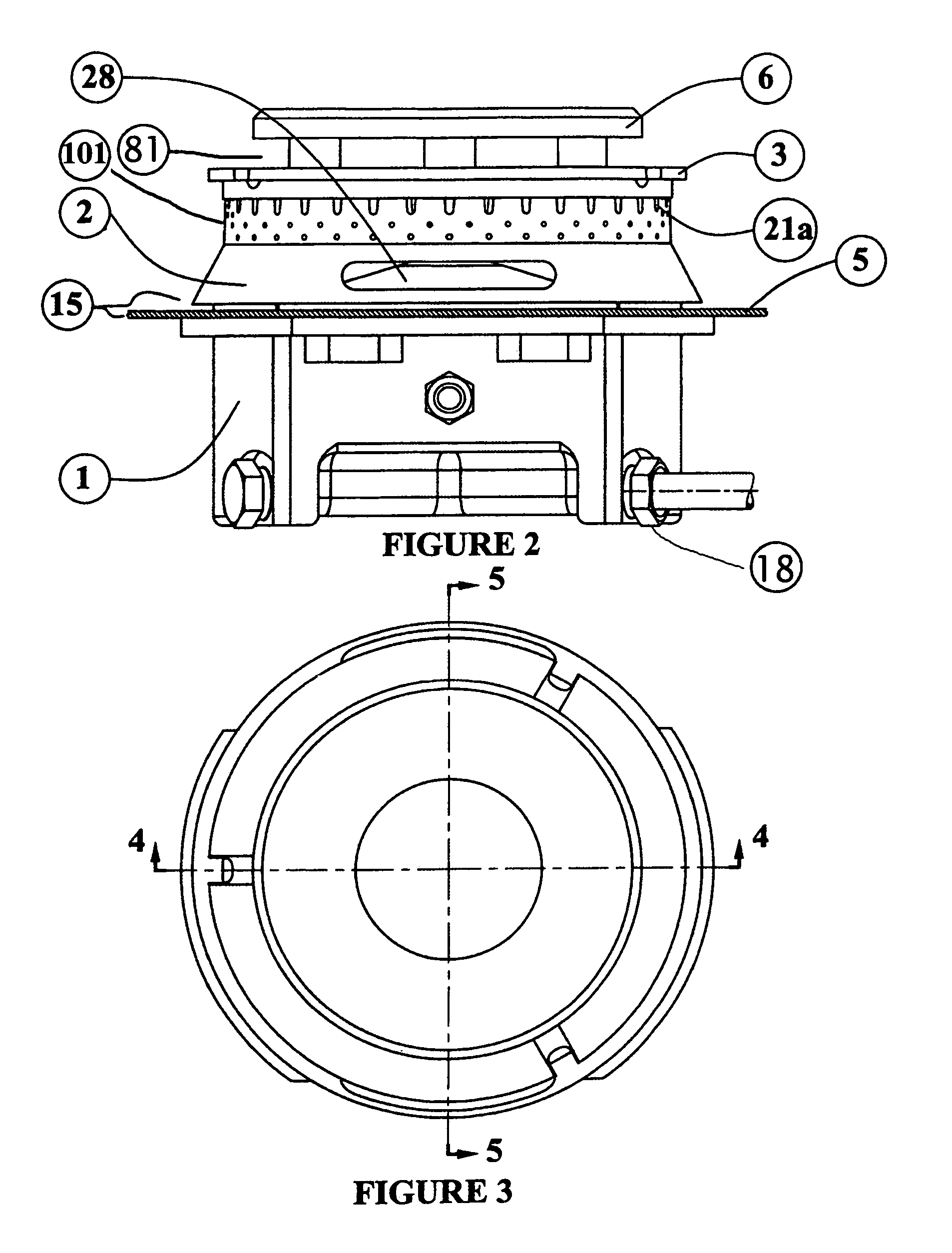
[0044]FIG. 1 shows an exploded view of the gas burner assembly or burner assembly (100). With respect to FIG. 1, a gas burner assembly (100) is shown. The gas burner assembly (100) consists of a mixing cup (1). In FIGS. 2, 4, 5 and 8 the mixing cup (1) is generally attached either to a transverse member (7) of an appliance or the base and / or the top (5) of the appliance. A burner base (2) is shown resting on the mixing cup (1). The burner base (2) is offset from the mixing cup (1) creating an open air passage or primary air slot (15). The primary air slot (15) allows air into a primary air inlet chamber (9). The present invention shows that there are at least two primary air inlet chambers (9) that feed a main burner chamber (35) that feed a first, second, third and fourth flame ring (21,22,23,24, respectively) as shown in FIG. 13.

[0045]A cover plate (6) is mounted on top of a burner cap (3). The number of flame rings that are necessary on the outer wall (101) of the main burner cha...


PUM


Abstract

This invention describes an improved gas burner assembly that can be adapted to attach to a range top or cooktop, or the floor of the range and can draw air from either above the range top level by external vents or from below range top level through an open style mixing cup. The invention uses a plurality of different flame rings to provide the user a wide variety of temperature settings starting from a low intensity simmer to high intensity cooking heat. The gas burner also utilizes a cover plate of transparent or translucent, heat proof material that allows the user to observe the interior of the burner to see if any of the flame rings have been ignited. The cover plate also transfers heat from the internal flame rings to the cooking utensil which provides a more uniform transfer of heat to the utensil.

Description

PRIORITY[0001]This application claims priority for Provisional Application 60 / 717,118.BACKGROUND OF THE INVENTIONField of the Invention[0002]This invention relates to the field of gas burners that are used in the home. Specifically, these burners are used in home appliances that in most cases have oven ranges.SUMMARY OF THE INVENTION[0003]Gas burners generally come in different sizes. The size generally will define the maximum BTU output of the gas burner. Depending upon the design of the flame rings of the specific burners, gas burners generally have a maximum output of approximately 15,000 BTU's (British Thermal Units), and have a diameter of approximately 4 inches (102 mm). The maximum BTU output is also governed by the flame density of the burner ring, or the ring that has the holes for the flame. The current state of the art in gas burners has a low intensity (low BTU output) gas burner that is regulated only by the amount of fuel / air mixture that is allowed through the flame r...

Claims


Application Information

Patent Timeline
Patent Type & Authority Patents(United States)
IPC IPC(8): F23D14/64F23D14/20F23D14/84F23D14/62
CPCF23D14/06F23D2212/00F23D2900/14061F23D2900/14063F23D2900/14062
Inventor HARNEIT, UWE
Owner DESIGNGASPARTS
Why Eureka
Try Eureka