

Indwelling urinary catheterization assembly
a catheterization and bladder technology, applied in the field of catheterization devices and methods of the urinary bladder, can solve the problems of infection of the patient's urinary tract, morbidity and additional costs for the patient and society, and the difficulty of maintaining a “sterile” environment during the procedur
- Summary
- Abstract
- Description
- Claims
- Application Information
AI Technical Summary
Benefits of technology
Problems solved by technology
Method used
Image

Examples
Embodiment Construction
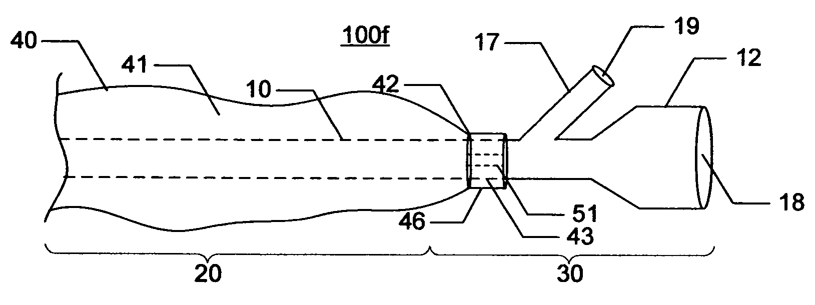
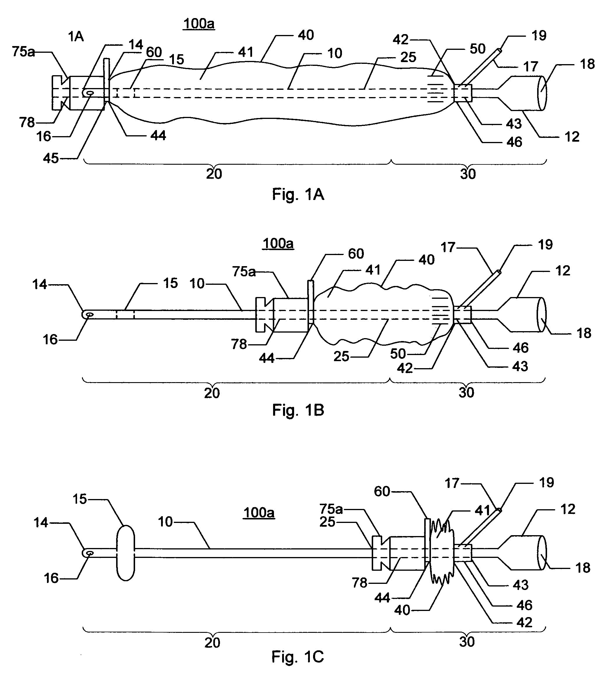
[0034]The present invention provides for catheter and catheter assemblies capable of mating with adhesive pads in order to increase a catheterized patient's mobility and prevent movement of the catheter in and out (pistoning) of
[0035]The following discussion is directed to various embodiments of the invention. Although one or more of these embodiments may be preferred, the embodiments disclosed should not be interpreted, or otherwise used, as limiting the scope of the disclosure, including the claims. In addition, one skilled in the art will understand that the following description has broad application, and the discussion of any embodiment is meant only to be exemplary of that embodiment, and not intended to intimate that the scope of the disclosure, including the claims, is limited to that embodiment.
[0036]Certain terms are used throughout the following description and claims to refer to particular system components. As one skilled in the art will appreciate, different persons ma...
PUM
 Abstract
Description
Claims
Application Information