Drain separator

a separator and draining technology, applied in the direction of steam separation arrangement, separation process, centrifuge, etc., can solve the problems of inconvenient cleaning inability to clean the rotor, etc., and achieve the effect of simple structure capable of separation

Active Publication Date: 2010-02-16
SMC CORP
View PDF29 Cites 21 Cited by
  • Summary
  • Abstract
  • Description
  • Claims
  • Application Information

AI Technical Summary

Benefits of technology

[0013]A general object of the present invention is to provide a drain separator which has a simple structure capable of separating a gas component and a liquid component from a mixture fluid reliably and stably at all times irrelevant to the flow state of the mixture fluid.

Problems solved by technology

Therefore, it is difficult to centrifuge steam and water contained in the gas-water mixture fluid under the rotating action of the revolving vane 4.
Therefore, the electric motor 12 for rotating the rotor 14 may be large-sized, and the structure of the rotor 14 may be complicated, inadvantegeously.
Further, because the shape of the liquid discharge flow passage 16 is complicated, when the liquid separated from the gas-liquid mixture gas flows, clog-up tends to occur due to the dust or the like contained in the liquid.

Method used


Image

  • Drain separator
  • Drain separator
  • Drain separator

Examples


first embodiment

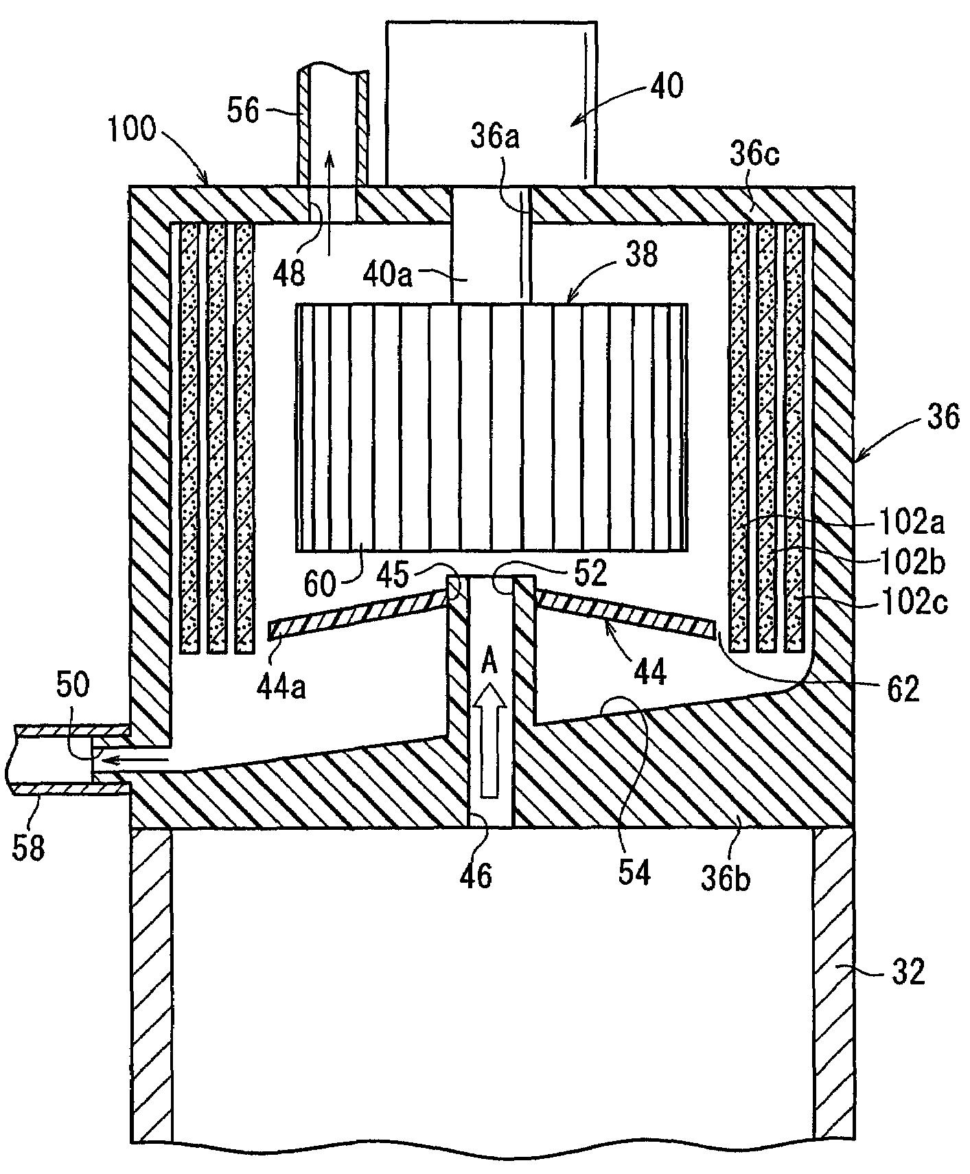
[0022]With reference to FIG. 1, reference numeral 30 represents a steam-generating unit to which a drain separator according to the present invention is applied.

[0023]The steam-generating unit 30 is used to generate saturated steam for driving a turbine in, for example, a pressurized water reactor. The steam-generating unit 30 includes a steam flow tube 32 extends in the vertical direction. A drain separator 34 is provided at the upper end of the steam flow tube 32. The saturated steam A, which is a mixture gas of steam and hot water flows upwardly through the steam flow tube 32.

[0024]The drain separator 34 includes a housing (body) 36 connected to the upper end of the steam flow tube 32, a fan (rotary member) 38 arranged rotatably in the housing 36, a driving section 40 installed in the housing 36, the driving section driving and rotating the fan 38, a cylindrical separating wall 42 provided at a position separated from the outer circumference of the fan 38 by a predetermined dista...

third embodiment

[0054]Next, a drain separator 120 is shown in FIG. 3.

[0055]The drain separator 120 according to the third embodiment is different from the drain separator 34 according to the first embodiment in that a discharge valve 122 is provided for the outlet port 50 from which the hot water separated in the housing 36 is discharged.

[0056]The discharge valve 122 is provided between the outlet port 50 and the piping 58 for discharging the hot water to the outside, and functions as a changeover mechanism for switching the communication state between the outlet port 50 and the piping 58. When the discharge valve 122 is in the valve-open state to communicate the outlet port 50 with the piping 58, hot water separated by the drain separator 120 can be discharged from the outlet port 50 via the discharge valve 122 to the piping 58.

[0057]On the other hand, when the discharge valve 122 is in the valve-closed state to shut off the communication between the outlet port 50 and the piping 58, the hot wate...

fourth embodiment

[0059]Next, a drain separator 140 is shown in FIG. 4.

[0060]The drain separator 140 according to the fourth embodiment is different from the drain separator 34 according to the first embodiment in that a second separating wall 144 is provided at the other end 36c of the housing 36 so that the second separating wall 144 opposes to the upper end surface of the fan 38, the second separating wall 144 being provided distinctly from a first separating wall 142 provided on the outer circumference side of the fan 38.

[0061]The drain separator 140 comprises the cylindrical first separating wall 142 which is provided around the outer circumference of the fan 38, and the disk-shaped second separating wall 144 which is provided on the inner wall surface of the other end 36c of the housing 36 between the driving section 40 and the upper end surface of the fan 38. The drive shaft 40a passes through a substantially central portion of the second separating wall 144 formed of a porous metal material ...


PUM

PropertyMeasurementUnit
velocityaaaaaaaaaa
flow velocityaaaaaaaaaa
flow rateaaaaaaaaaa

Abstract

A driving section is provided for a housing. A fan is rotated in the housing by the driving section. Saturated steam, which is supplied to the housing, is separated into a liquid component and a gas component by applying the centrifugal force to the saturated steam by the fan to make the saturated steam pass through a cylindrical separating wall. The liquid component is discharged from an outlet port of the housing by the separating wall and a shielding section. On the other hand, the gas component is discharged from a discharge port formed at an upper portion of the housing.

Description

BACKGROUND OF THE INVENTION[0001]1. Field of the Invention[0002]The present invention relates to a drain separator for separating a gas component and a liquid component from a mixture fluid containing a gas and a liquid.[0003]2. Description of the Related Art[0004]A gas / liquid separator (drain separator) has been hitherto known, in which, for example, a separator is applied to a steam-generating unit for generating steam containing water so that the gas-water mixture fluid generated by the steam-generating unit is separated into a gas component (steam) and a liquid component (water).[0005]In the case of a steam-generating unit 2 shown in FIG. 6 to which a gas / liquid separator is applied, a revolving vane 4, which has a plurality of blades, is provided rotatably in a cylindrical gas-water ascending tube 3. A cylindrical water-falling barrel 5 is provided to cover the gas-water ascending tube 3 around the gas-water ascending tube 3. A space 6 is formed between the water-falling barrel...

Claims


Application Information

Patent Timeline
Patent Type & Authority Patents(United States)
IPC IPC(8): B01D45/12B01D45/14
CPCB01D45/14B01D50/002B04B5/12F22B37/32B01D50/20B01D19/00
Inventor FUKANO, YOSHIHIROMURAI, TAKAYUKI
Owner SMC CORP
Why Eureka
Try Eureka