Nonwoven fabric

a technology of nonwoven fabric and fibers, applied in the field of nonwoven fabrics, can solve the problems of high-density fibers, entanglement of fibers, and inability to adjust the orientation or arrangement of fibers in the fibrous layer,

Inactive Publication Date: 2010-02-16
UNI CHARM CORP
View PDF31 Cites 112 Cited by
  • Summary
  • Abstract
  • Description
  • Claims
  • Application Information

AI Technical Summary

Benefits of technology

[0012]It is an object of the present invention is to provide nonwoven fabric that easily pass liquids, such as excreta, and have concave and convex portions.
[0013]The inventors recognized that it is possible to manufacture nonwoven fabric that easily pass liquids, and have concave and convex portions by moving fibers composing a fiber web, supported from a bottom surface side by a predetermined air-permeable support member, while blowing a gas from a top surface side, and completed the invention.
[0034]The present invention provides nonwoven fabric formed with at least a groove portion and convex shapes, and allows the easy penetration of a predetermined liquid, such excreta.

Problems solved by technology

However, these methods only entangle the fibers and do not adjust the orientation or the arrangement of the fibers in the fibrous layer, or the shape of the fibrous layer.
The result is high-density fibers, with low liquid-penetrability in many of the thermally-bonded areas.
If the thermally bonded area turns into a film, it is even more difficult for the liquid to penetrate downward quickly.
Therefore, the manufacturing processes are complicated.
This causes the problem of a thermally bonded area not being able to quickly pass a predetermined liquid of excreta, and the like.

Method used


Image

  • Nonwoven fabric
  • Nonwoven fabric
  • Nonwoven fabric

Examples


first embodiment

1. FIRST EMBODIMENT OF THE NONWOVEN FABRIC

[0058]FIGS. 2A to 5 explain the first embodiment of the nonwoven fabric of the present invention.

1-1. Shapes

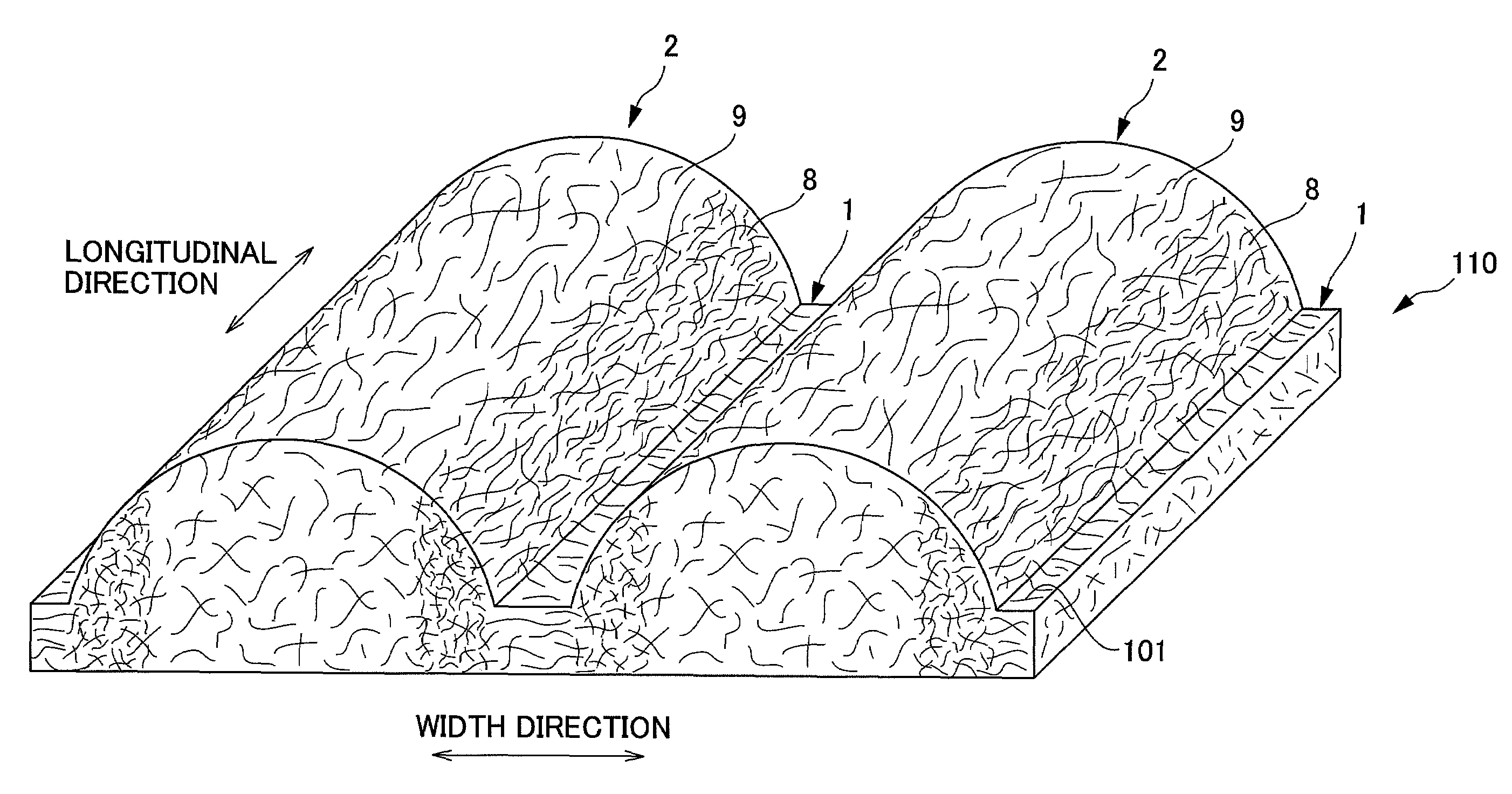
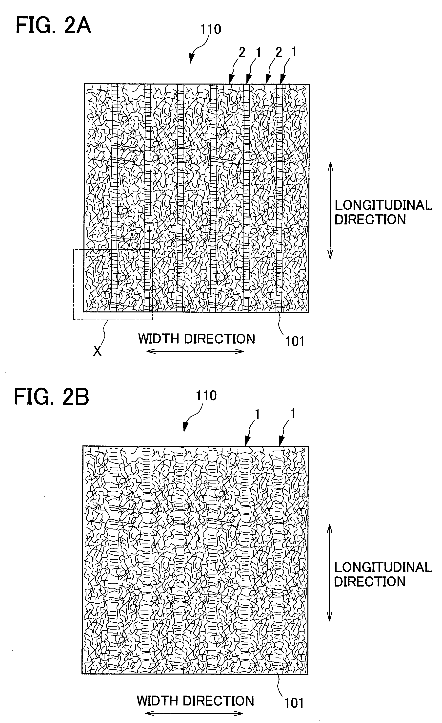
[0059]As shown in FIGS. 2A, B and FIG. 3, a plurality of groove portions 1 is formed in parallel at substantially equidistant spacing along a first direction (hereinafter referred to as a longitudinal direction) on a first side of the nonwoven fabric 110 according to this embodiment. In this embodiment, the plurality of groove portions 1 is formed in parallel at equidistance spacing, but this is not meant to be a limitation. The spacing between adjacent groove portions 1 can be different. It is also acceptable that the spacing of the groove portions 1 is not parallel, but varied.

[0060]Furthermore, raised ridge portions 2 are formed between two adjacent groove portions 1 and 1. A plurality of raised ridge portions 2 and 2 are formed in parallel at equidistant spacing, in the same way as the groove portions 1. The heights (the thickness ...

second embodiment

2-1. Second Embodiment

[0113]FIGS. 10 and 11 explain the second embodiment of the nonwoven fabric of the present invention.

2-1-1. Nonwoven Fabric

[0114]As shown in FIGS. 10 and 11, the nonwoven fabric 116 of the second embodiment are different from the first embodiment in the point that the overall nonwoven fabric 116 are rolling in a wave shape. The following will now explain the points that are different to the first embodiment.

[0115]The nonwoven fabric 116 of the second embodiment has rolling wave-shapes substantially perpendicular to the direction that the groove portions 1 and raised ridge portions extend.

2-1-2. Manufacturing Method

[0116]The method for manufacturing the nonwoven fabric 116 of the second embodiment is the same as the method used for the first embodiment, but the configuration of a mesh supporting member 260 that is the air-permeable support member is different. The mesh supporting member 260 of the second embodiment is formed by weaving a plurality of wires 261 of...

third embodiment

2-2. Third Embodiment

[0123]FIG. 12 explains the third embodiment of the nonwoven fabric of the present invention.

[0124]As shown in FIG. 12, the shapes of the surfaces opposite to the surfaces formed with the raised ridge portions 2 of the nonwoven fabric 140 are different from those of the first embodiment. The following will now explain the points that are different to the first embodiment.

2-2-1. Nonwoven Fabric

[0125]The groove portions 1 and raised ridge portions 2 are alternately formed in parallel on the first surface side of the nonwoven fabric 140 of the third embodiment. Also, the area of the bottom surface of the raised ridge portions 2 is formed to project to the side that the raised ridge portions 2 projects, on the second surface side of the nonwoven fabric 140. Said another way, the areas of the bottom surfaces on the second side of the raised ridge portions 2 of the nonwoven fabric 140 form indented concave portions. Also, the areas of the second side at the bottom surf...


PUM

PropertyMeasurementUnit
thicknessaaaaaaaaaa
thicknessaaaaaaaaaa
densityaaaaaaaaaa

Abstract

Nonwoven fabric has a plurality of groove portions continuously formed along a predetermined direction, and a plurality of raised ridge portions formed continuously along the groove portions, each adjacent to the groove portions. The basis weight is the least, and the content percentage of laterally-oriented fibers is high, and the content percentage of longitudinally-oriented fibers is low at the groove portions of the nonwoven fabric. Sides at the raised ridge portions are formed so that their basis weight is the greatest, and the content percentage of the fiber oriented toward a longitudinal direction is high.

Description

[0001]This application is based on and claims the benefit of priority from Japanese Patent Application No. 2006-174505, filed on 23 Jun. 2006 and Japanese Patent Application No. 2006-270108, filed on 29 Sep. 2006, the content of which are incorporated herein by reference.BACKGROUND OF THE INVENTION[0002]1. Field of the Invention[0003]The present invention relates to nonwoven fabric.[0004]2. Related Art[0005]Conventionally, nonwoven fabrics are used in a wide range of fields from hygienic products, such as baby diapers or feminine care articles (sanitary napkins) to cleaning products, such as wipers, or medical products, such as masks. Such nonwoven fabric is used in many different fields, but when actually used in products of each of those fields, it is necessary that the nonwoven fabric is manufactured with the properties and structures appropriate for their intended use.[0006]Nonwoven fabric is manufactured by forming a fibrous layer (fiber web) using a dry method or a wet method,...

Claims


Application Information

Patent Timeline
Patent Type & Authority Patents(United States)
IPC IPC(8): B32B3/00B32B3/28B32B3/30B32B5/14A61F13/49A61F13/511A61F13/53D04H1/70
CPCD04H1/54D04H1/58Y10T428/24479Y10T428/24595Y10T428/24537Y10T428/24612Y10T428/2457D04H1/76D04H1/70
Inventor NODA, YUKIISHIKAWA, HIDEYUKIMIZUTANI, SATOSHIKIMURA, AKIHIRO
Owner UNI CHARM CORP
Why Eureka
Try Eureka