Supercharge Your Innovation With Domain-Expert AI Agents!

Current-mode differential transmitter and receiver

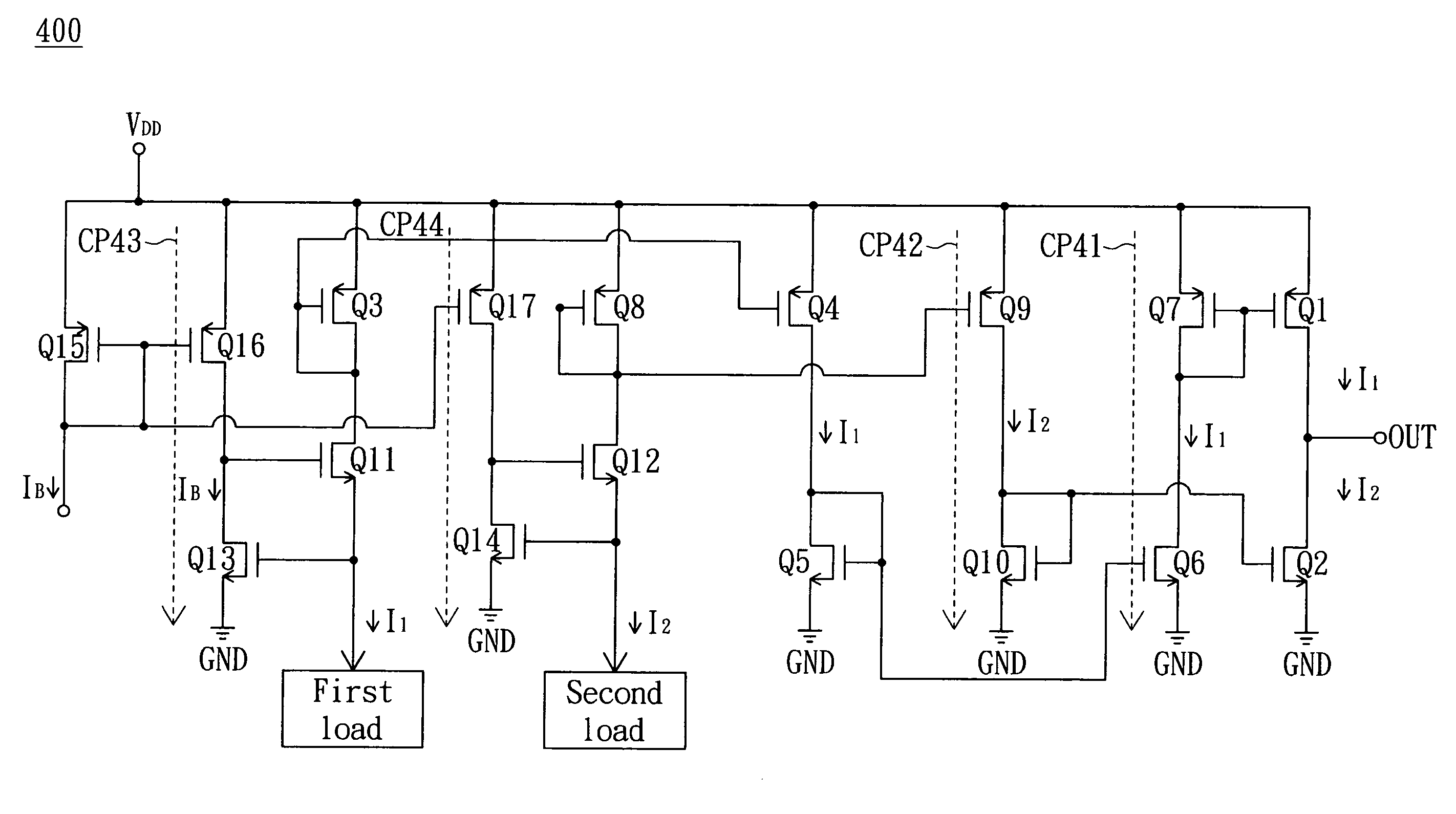
a transmitter and receiver technology, applied in the field of current-mode differential transmitters and receivers, can solve problems such as noise interference, and achieve the effect of large data swing and low nois

Inactive Publication Date: 2010-02-16
HIMAX TECH LTD
View PDF5 Cites 0 Cited by
  • Summary
  • Abstract
  • Description
  • Claims
  • Application Information

AI Technical Summary

Benefits of technology

The design achieves double the data swing of conventional current-mode transmitters while significantly reducing noise interference, ensuring reliable signal transmission by leveraging the difference between positive and negative current signals.

Problems solved by technology

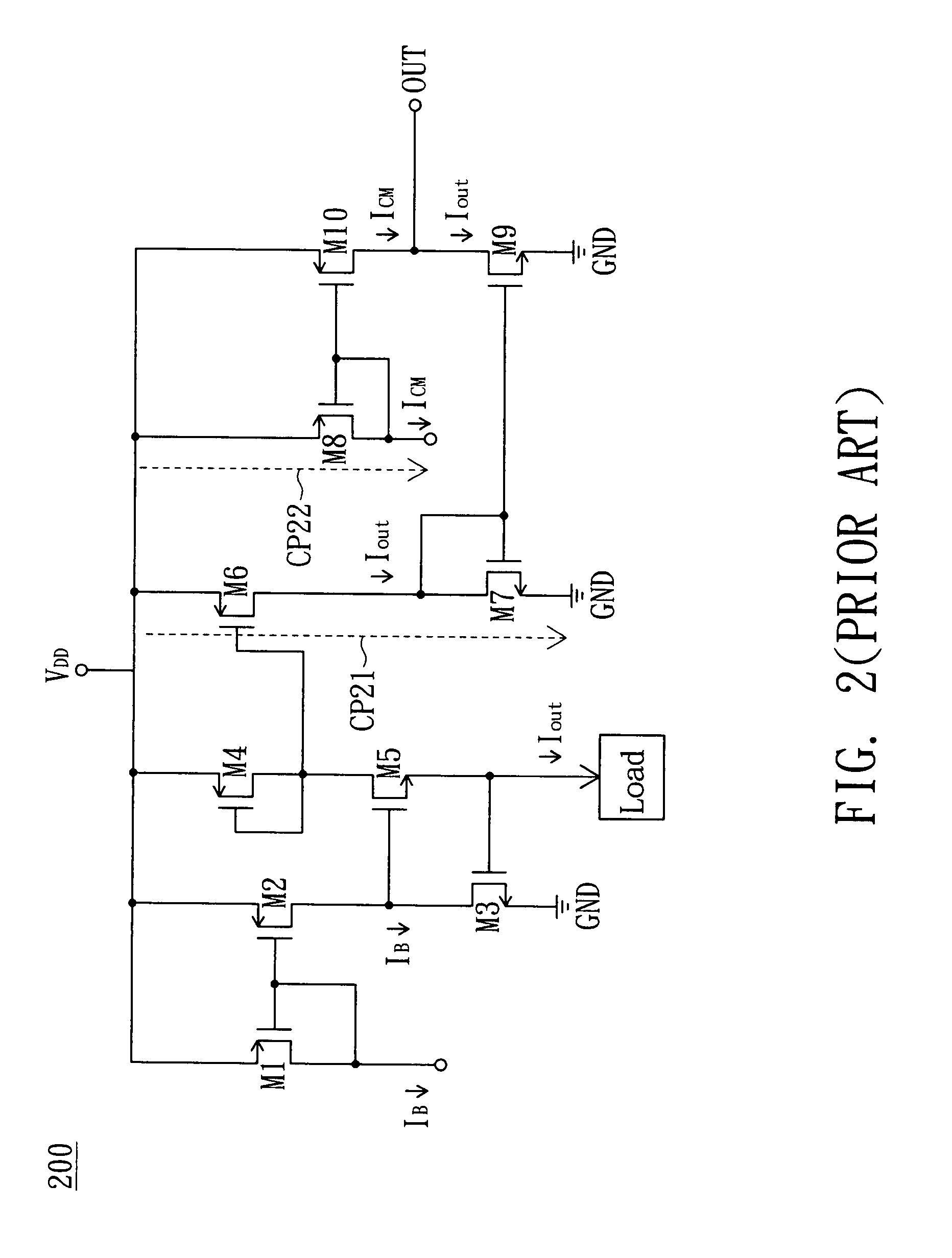
The above-mentioned current-mode transmitter and receiver both have a form of single-end output or input and thus are subject to noise interference.

Method used


Image

  • Current-mode differential transmitter and receiver
  • Current-mode differential transmitter and receiver
  • Current-mode differential transmitter and receiver

Examples


Embodiment Construction

[0019]FIG. 3A shows a circuit diagram of a current-mode differential transmitter according to a preferred embodiment of the invention. The current-mode differential transmitter 300 receives a single-end input voltage signal VI, and accordingly generates a differential output current signal derived from a positive-end current signal IPout and a negative-end current signal INout. The current-mode differential transmitter 300 includes four switches SW1˜SW4 implemented by NMOS transistors, and a current mirror composed of NMOS transistors M1˜M8.

[0020]The first switch SW1 is coupled in a current path CP31 and controlled by the single-end input voltage signal VI. The second switch SW2 is coupled in a current path CP32 and controlled by an inverted signal VIB of the single-end input voltage signal VI. The third switch SW3 has one end receiving a supply voltage VDD and the other end coupled to one end of the first switch SW1, and controlled by the inverted signal VIB of the single-end input...


PUM


Abstract

A current-mode differential transmitter, receiving a single-end input voltage signal and accordingly generating a differential output current signal, is provided. The transmitter includes a first switch, a second switch and a current mirror. The first switch is coupled in a first current path and controlled by the single-end input voltage signal. The second switch is coupled in a second current path and controlled by an inverted signal of the single-end input voltage signal. The current mirror mirrors a reference current to the first current path when the first switch is turned on, and mirrors the reference current to the second current path when the second switch is turned on. The differential output current signal is derived from the currents on the first and second current paths.

Description

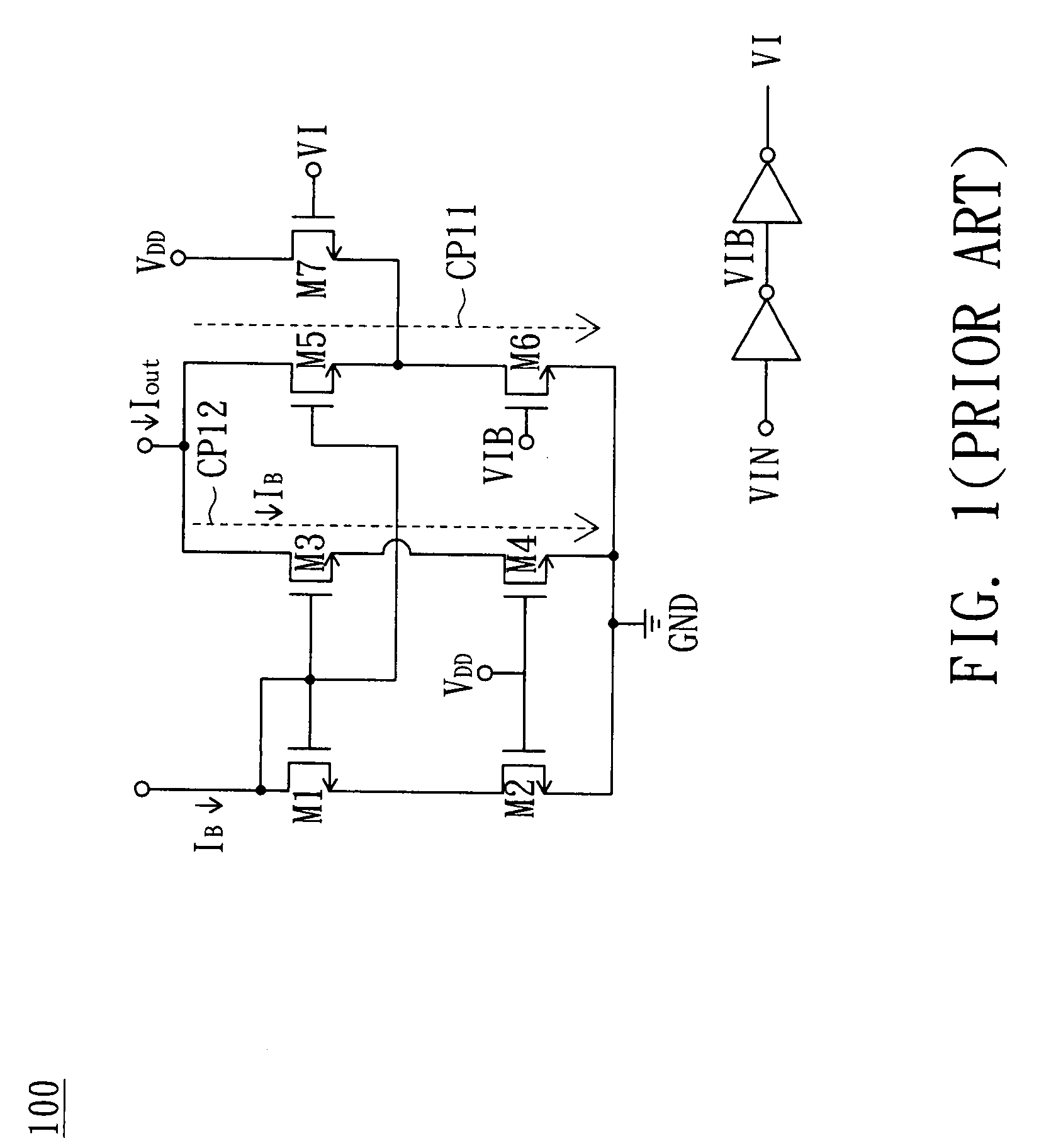
BACKGROUND OF THE INVENTION[0001]1. Field of the Invention[0002]The invention relates in general to a current-mode differential transmitter and receiver and more particularly to a current-mode differential transmitter and receiver with low noise and large data swing.[0003]2. Description of the Related Art[0004]FIG. 1 shows a circuit diagram of a conventional current-mode transmitter. The current-mode transmitter 100 receives an input voltage signal VI, and accordingly generates an output current signal Iout. The current-mode transmitter 100 includes two switches implemented by NMOS transistors M6 and M7, and a current mirror composed of NMOS transistors M1˜M5. The switch M6 is coupled in a current path CP11 and controlled by the input voltage signal VI. The switch M7 has one end receiving a supply voltage VDD and the other end coupled to one end of the switch M6, and controlled by the inverted signal VIB of the input voltage signal VI.[0005]The current mirror mirrors a reference cur...

Claims


Application Information

Patent Timeline
Patent Type & Authority Patents(United States)
IPC IPC(8): H02M11/00
CPCH04L25/0278
Inventor HUANG, CHIH-HAURCHU, YUAN-KAI
Owner HIMAX TECH LTD
Features
  • R&D
  • Intellectual Property
  • Life Sciences
  • Materials
  • Tech Scout
  • Unparalleled Data Quality
  • Higher Quality Content
  • 60% Fewer Hallucinations
Learn More