Approach for controlling audio signals in remote location

Active Publication Date: 2010-02-16
ELAN HOME SYST L L C
View PDF15 Cites 13 Cited by
  • Summary
  • Abstract
  • Description
  • Claims
  • Application Information

AI Technical Summary

Benefits of technology

[0010]The present invention is directed to overcoming the above-mentioned challenges and others related to the types of approaches and implementations discussed above and in other applications. The present invention is exemplified in a number of implementations and applications, some of which are summarized below.
[0011]According to an example embodiment of the present invention, a facility-wide audio distribution system delivers controlled audio to user-controlled speaker loads located in remote audio zones. The system includes an audio distribution controller having at least one power amplifier for generating at least one audio signal, and a load arrangement located remote from the audio distribution controller and adapted to receive user-control signals in at least one co-located one of the remote audio zones. The load arrangement includes a speaker load circuit and an isolation circuit for generating at least one transformed audio signal for the speaker load circuit. The isolation circuit is adapted to provide an impedance-matched termination for said at least one audio signal, and the speaker load circuit is adapted to delivering audible signals in the co-located one of the remote audio zones and in response to the user-control signals.
[0012]According to anoth

Problems solved by technology

For some audio systems, a user can not control the audio system from a remote zone.
The user must inconveniently go to the central location of the audio system to control the audio music for the remote zone where the user is located.
The digital control circuits do not include advanced software control functions and are limited to an incremental up/down control.
However, the two piece design in

Method used


Image

  • Approach for controlling audio signals in remote location
  • Approach for controlling audio signals in remote location
  • Approach for controlling audio signals in remote location

Examples


Embodiment Construction

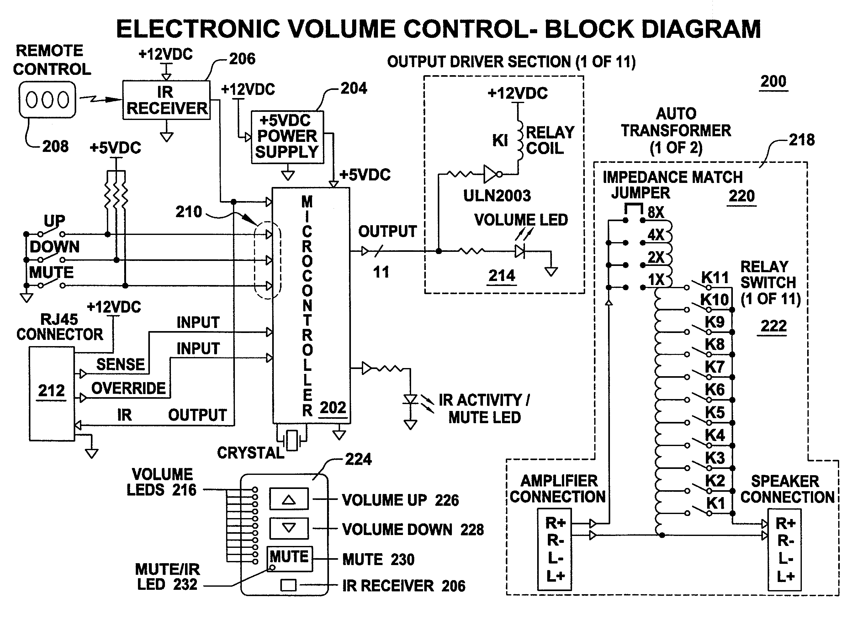
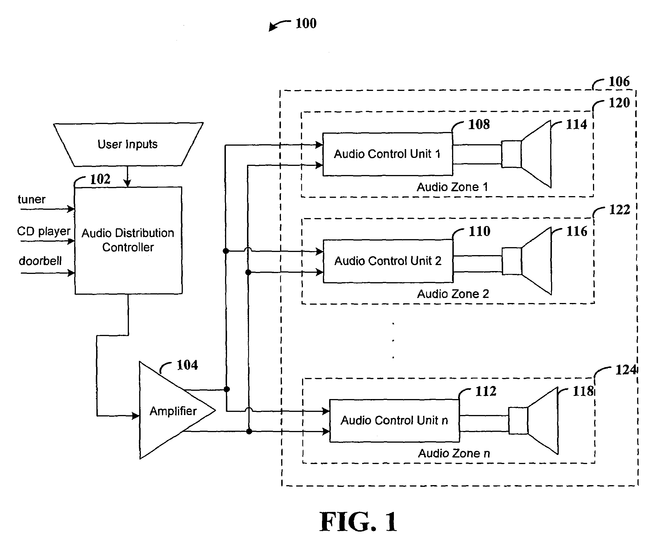
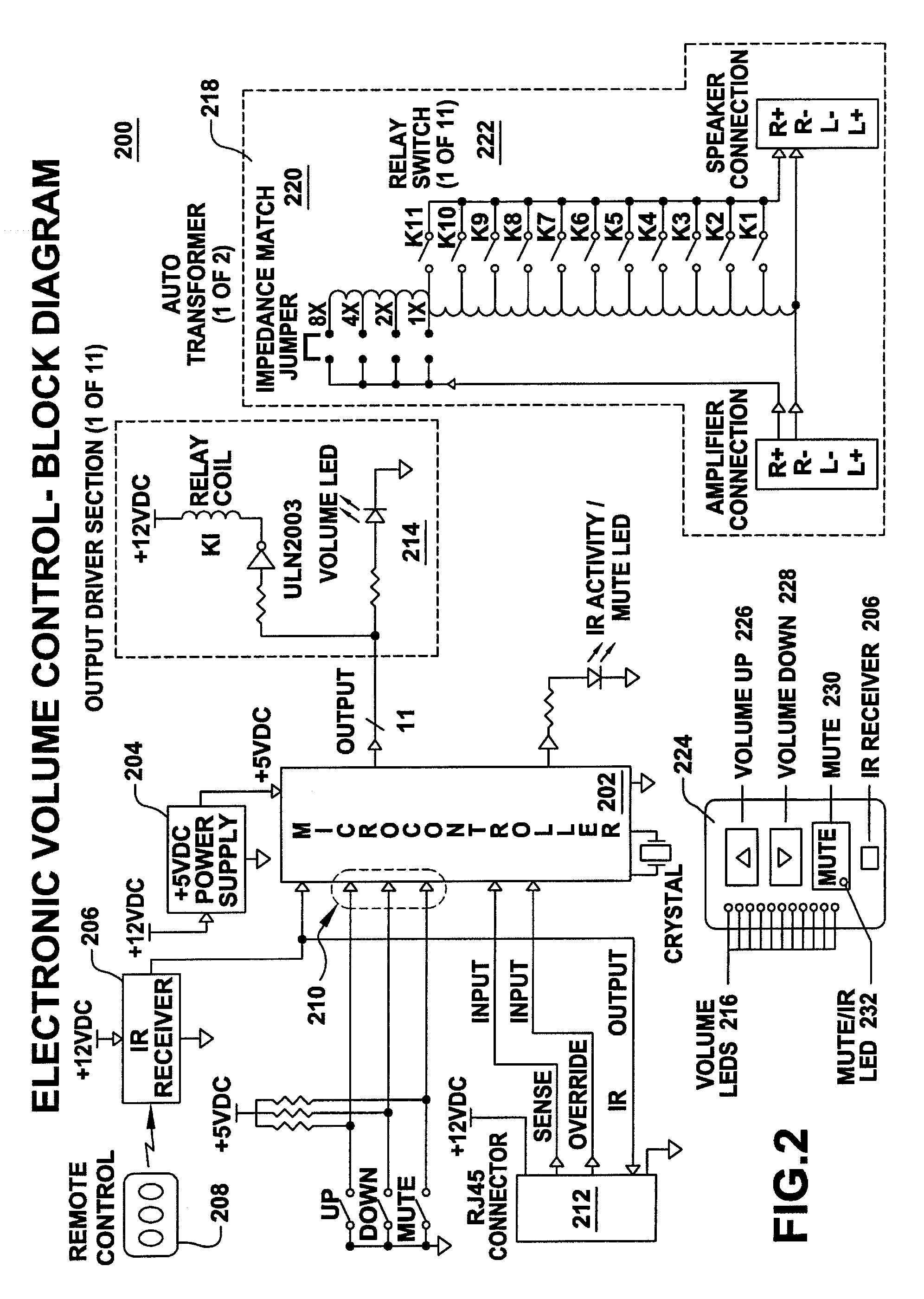
[0019]The present invention is believed to be applicable to a variety of facility applications utilizing an audio system. The present invention has been found to be particularly advantageous for a facility application in which audio is sent by an audio system to one or more audio zones. The present invention includes audio control units located in each audio zone. The audio control units enable a user to conveniently control local audio volume while located in an audio zone. Impedance matching circuits in the audio control units allow each power amplifier in an audio system to safely deliver the power amplifier output audio signal to speaker loads without overloading the power amplifier and / or independent of volume adjustment. The present invention is not necessarily limited to such applications; various aspects of the invention may be appreciated through a discussion of various examples using this context.

[0020]According to an example embodiment of the present invention, an audio s...


PUM


Abstract

An example embodiment is directed to use in a facility benefiting from the distribution of audio throughout different facility zones (“audio zones”), with each audio zone receiving an audio signal from a remotely-located audio distribution controller. For controlling audio at a user-controlled speaker load located in one of the audio zones, a circuit arrangement includes isolation circuit, speaker load circuit, user-input device and an audio control unit. The isolation circuit generates a transformed audio signal by provide an impedance-matched termination and by permitting one of a number of impedance-matching circuits to be set wherein each impedance-matching circuit provides a different amount of electrical power to the speaker load. The speaker load circuit delivers, in response to the transformed audio signal, audible signals in the audio zone. The audio control unit has a microprocessor adapted to control the delivery of the audible signals in response to the input commands generated via the user-input device.

Description

RELATED PATENT DOCUMENTS[0001]This is a conversion of U.S. Provisional Patent Application Ser. No. 60 / 435,424, entitled “Universal Electronic Volume Control,” and filed on Dec. 20, 2002, to which priority is claimed under 35 U.S.C. §119.FIELD OF THE INVENTION[0002]The present invention relates generally to control schemes for audio signals and more particularly for controlling centrally generated audio signals from remote locations.BACKGROUND OF THE INVENTION[0003]Audio systems are used in a variety of applications. These applications include consumer and professional applications. Professional applications include entertainment venues such as theaters. For many audio system applications, centrally generated audio is sent to one or more audio zones. For centrally generated audio the input sources are located together at a location that is denoted the central location. This central location can be anywhere in the facility. The centrally generated audio is derived from input sources s...

Claims


Application Information

Patent Timeline
IPC IPC(8): G03G11/00H04R29/00
CPCH04R29/007
Inventor CHRISTENSEN, STEVEFARINELLI, JR., ROBERT P.FISHER, RANDYNEWMAN, RAYMOND ANTHONY
Owner ELAN HOME SYST L L C
Why Eureka
Try Eureka