Apparatus and method to protect fiber ribbons

a fiber ribbon and apparatus technology, applied in the field of fiber cables, can solve the problems of higher cost and complexity disadvantage, and achieve the effects of avoiding kinking, bending, damage to the fiber ribbon, and saving cost and maintenan

Active Publication Date: 2010-02-16
MOWERY SR ARTHUR J
View PDF11 Cites 47 Cited by
  • Summary
  • Abstract
  • Description
  • Claims
  • Application Information

AI Technical Summary

Benefits of technology

[0013]Accordingly, it is an object of the present invention to provide an apparatus and method to protect fiber ribbons which supports individual ribbons extending beyond a fiber cable sheath. Design features allowing this object to be accomplished include a router having a body minor barrel bore, a cap having cap bores, a fiber cable disposed within the body minor barrel bore, fiber ribbon disposed within at least one cap bore, and a transportation tube around each ribbon extending through the cap bores. Advantages associated with the accomplishment of this object include avoiding kinking, bending, and damage to the fiber ribbons, along with the consequent cost and maintenance savings.
[0014]It is another object of the present invention to provide an apparatus and method to protect fiber ribbons which provides a cover to each fiber ribbon. Design features allowing this object to be accomplished include a cable entering a router through a router minor barrel bore, fiber ribbons extending through router cap bores, and transportation tubes covering the fiber ribbons which extend through the cap bores. Benefits associated with the accomplishment of this object include avoidance of damage to the fiber ribbons, and the associated cost and maintenance savings.
[0015]It is still another object of this invention to provide an apparatus and method to protect fiber ribbons which supports individual ribbons extending beyond a fiber cable sheath. Design features allowing this object to be accomplished include a router having a body minor barrel bore, a cap having cap bores, a fiber cable disposed within the body minor barrel bore, fiber ribbon disposed within at least one cap bore, and a transportation tube around each ribbon extending through the cap bores. Advantages associated with the accomplishment of this object include the reduction of repair costs, and the increase of reliability.

Problems solved by technology

U.S. Pat. Nos. 5,535,298, 6,510,273, 6,623,173 and 6,880,980 were granted Fasnacht et al, Ali et al, Grois et al., and Kang et al. respectively While these disclosed means to support fiber ribbons using transportation tubes, they suffered from the disadvantage of complexity, and therefore higher cost.

Method used


Image

  • Apparatus and method to protect fiber ribbons
  • Apparatus and method to protect fiber ribbons
  • Apparatus and method to protect fiber ribbons

Examples


Embodiment Construction

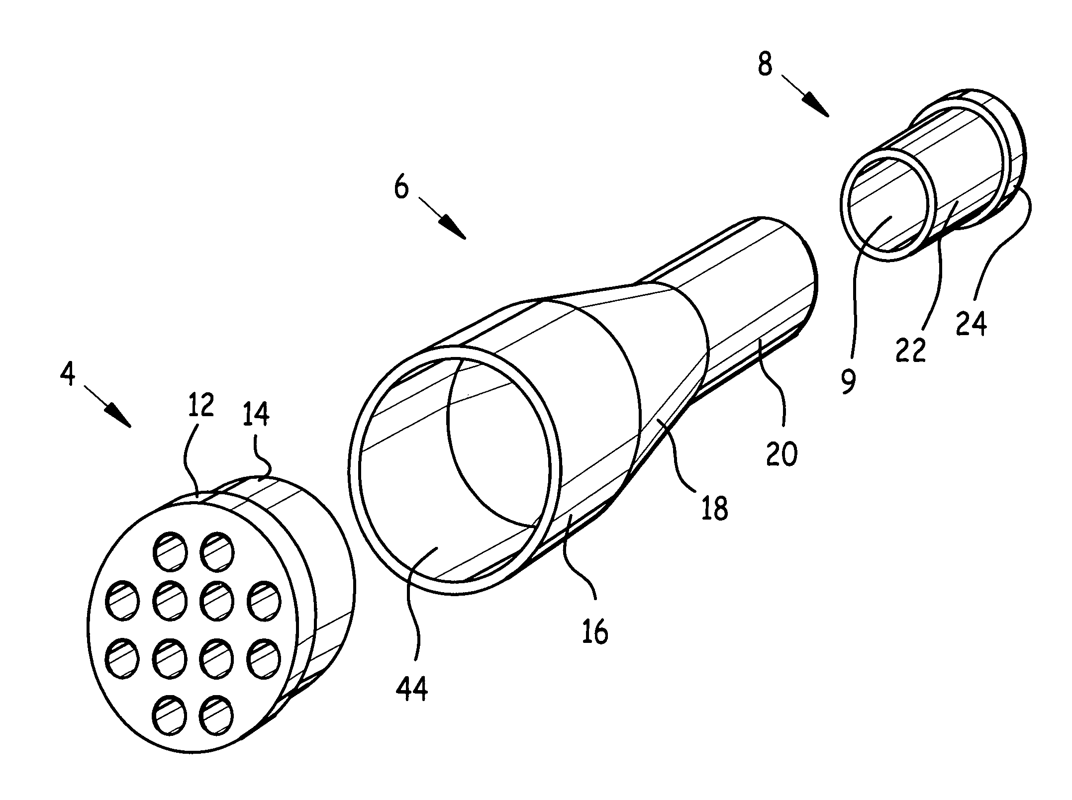
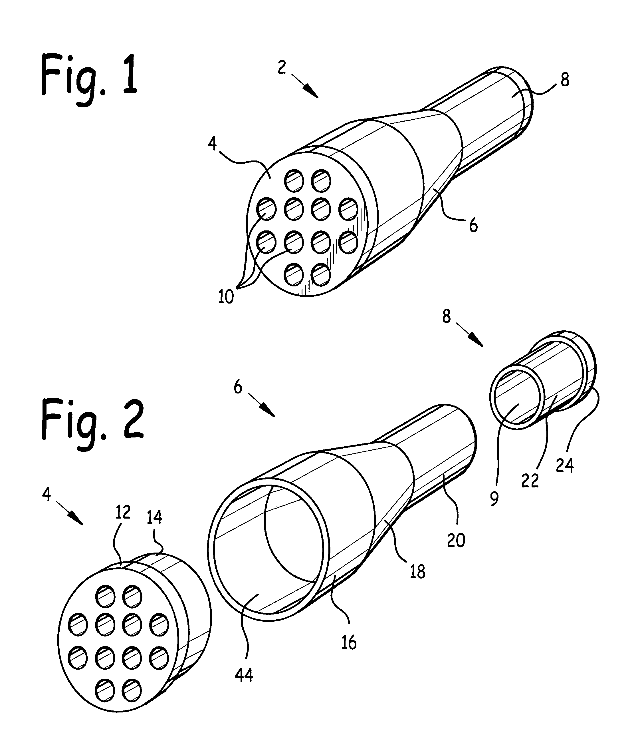
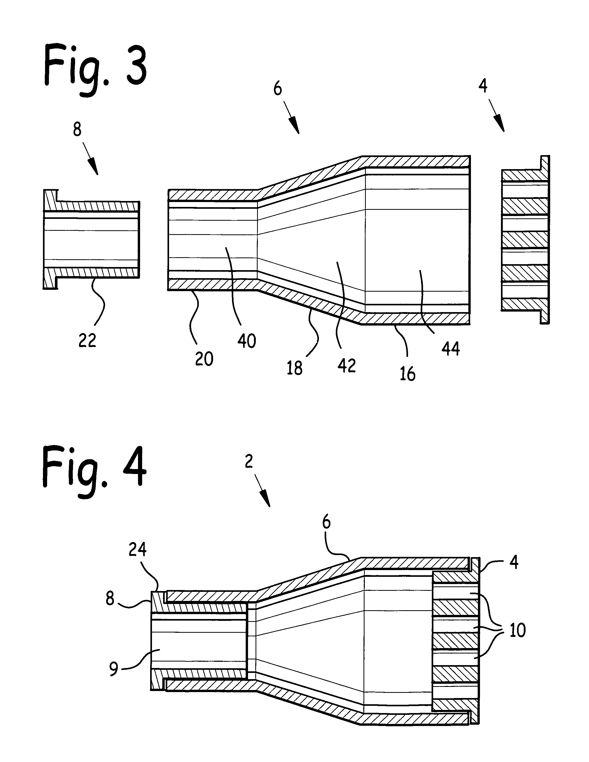
[0032]FIG. 1 is a front quarter elevated isometric view of router 2. FIG. 2 is a front quarter elevated isometric view the component parts of router 2. FIG. 3 is a side cross-sectional view of the component parts router 2. FIG. 4 is a side cross-sectional view of router 2.

[0033]Router 2 comprises cap 4, and optionally insert 8, frictionally inserted into body 6. Body 6 comprises body major barrel 16 rigidly attached to one end of body funnel 18, and body minor barrel 20 rigidly attached to an opposite end of body funnel 18. In the preferred embodiment, body major barrel 16 and body minor barrel 20 were substantially cylindrical, body funnel 18 was substantially a cone section, and body major barrel 16, body minor barrel 20, and body funnel 18 were substantially co-axial.

[0034]Body 6 comprises body minor barrel bore 40 in body minor barrel 20, body funnel bore 42 in body funnel 18, and body major barrel bore 44 in body major barrel 16. Body minor barrel bore 40, body funnel bore 42, ...


PUM


Abstract

An apparatus and method to protect fiber ribbons. A router having a body and cap are disclosed. Fiber cable sheath is stripped from one end, and the fiber ribbons thus exposed are inserted through the body and through cap bores in the cap. The cap is frictionally pushed into the body, and transportation tubes are installed over the fiber ribbons. The cap bores are sized to frictionally admit one end of a transportation tube, which has the effect of holding the transportation tubes in place. An optional insert is disclosed which has the function of reducing the body minor barrel bore diameter through which the fiber cable enters the router.

Description

BACKGROUND OF THE INVENTION[0001]1. Field of the Invention[0002]This invention relates to fiber cables, and in particular to an apparatus and method to protect fiber ribbons.[0003]2. Background of the Invention[0004]Fiber cable was invented in the early 1970s, and its use has grown to include telecommunications, medicine, military, automotive, and industrial. Telecommunications applications include global networks, local telephone exchanges, subscribers' homes, and desktop computers, and carry voice, data, or video over distances of ranging from a few feet to hundreds of miles.[0005]Optical fiber is frequently used for transmission of data signals in private networks, such as exist in manufacturing firms, banks, universities, financial firms, and more. These entities have a need for secure, reliable systems to transfer computer and monetary information between buildings to the desktop terminal or computer, and around the world. The security inherent in optical fiber systems is a maj...

Claims


Application Information

Patent Timeline
Patent Type & Authority Patents(United States)
IPC IPC(8): G02B6/00
CPCG02B6/3887G02B6/4471G02B6/4478
Inventor MOWERY, SR., ARTHUR J.
Owner MOWERY SR ARTHUR J
Why Eureka
Try Eureka