System for transmission/reception of e-mail with attached files

Inactive Publication Date: 2010-02-16
PANASONIC CORP
View PDF35 Cites 7 Cited by
  • Summary
  • Abstract
  • Description
  • Claims
  • Application Information

AI Technical Summary

Benefits of technology

[0012]To cope with the above-mentioned problem, the object of the present invention is to provide an e-mail transmission/reception system, a mail gateway, a mail terminal, a program recording medium, and a program by which, when using attached files that are included in the received e-mail (e.g., forwarding of e-mail), a user can select attached

Problems solved by technology

However, when sending e-mail with attached files to cellular phones and PHSs, the attached files are automatically deleted in most of the mobile Internet services.
However, according to the above-mentioned conventional system, when a plurality of attached files are included in the mail, there is a problem in that a file to be attached cannot be selected from the plurality o

Method used


Image

  • System for transmission/reception of e-mail with attached files
  • System for transmission/reception of e-mail with attached files
  • System for transmission/reception of e-mail with attached files

Examples


Example

First Embodiment

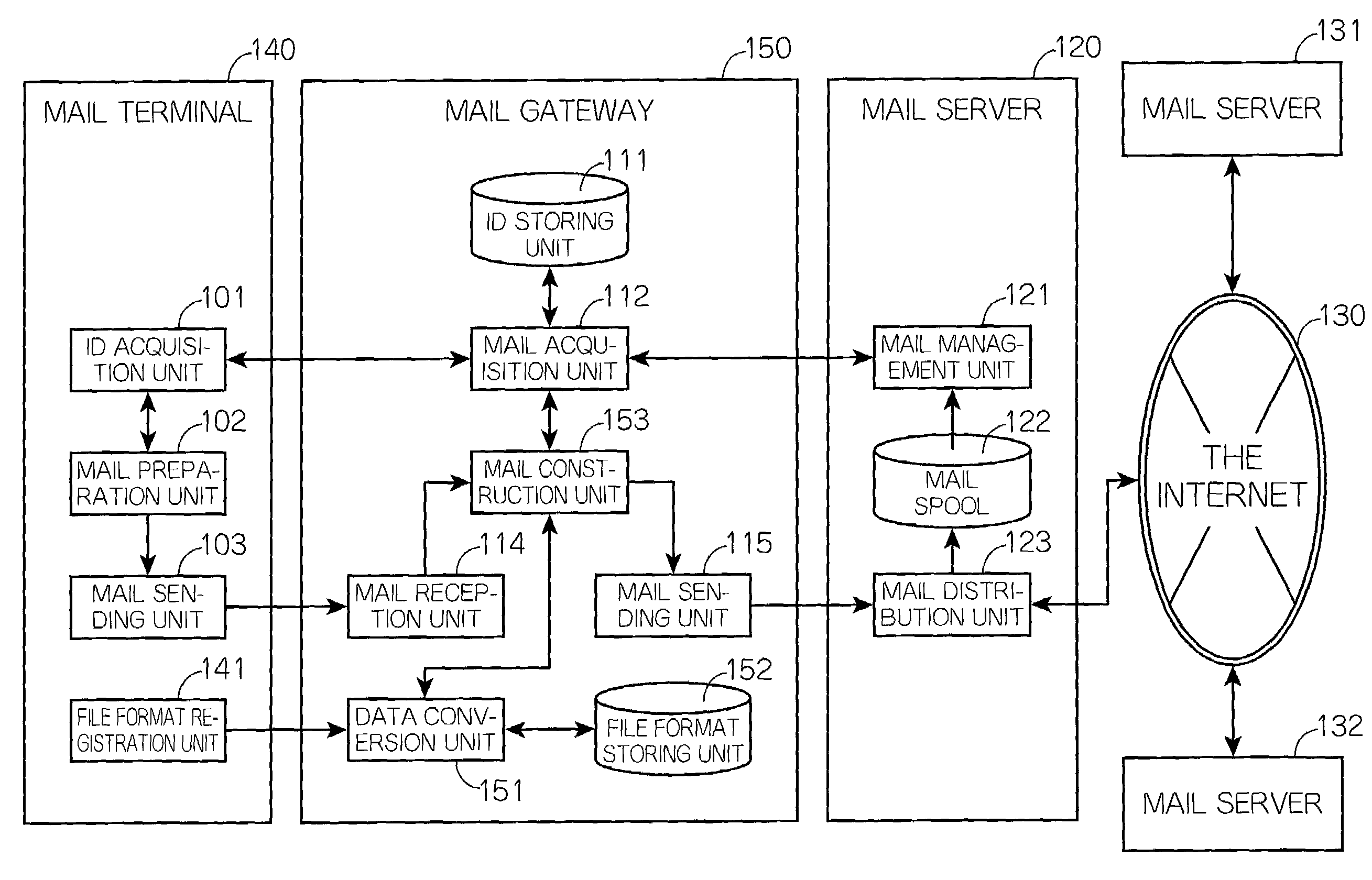
[0064]FIG. 1 is a block diagram showing the construction of the e-mail transmission / reception system according to the first embodiment of the present invention including a mail terminal 100, a mail gateway 110, and a mail server 120.

[Construction of the Mail Terminal 100]

[0065]As shown in FIG. 1, the mail terminal 100 consists of an ID acquisition unit 101, a mail preparation unit 102, and a mail sending unit 103.

[0066]The ID acquisition unit 101 issues an ID acquisition request to the mail gateway 110 to acquire a list of attached IDs from the mail gateway 110. The acquired list is passed to the mail preparation unit 102.

[0067]Here, the attached ID refers to an identifier that is generated for and corresponds to each of the attached files included in the mail (hereafter referred to as “received mail”) that the mail server 120 receives and stores for each user.

[0068]The mail preparation unit 102 prepares the mail that should be sent (hereafter referred to as “transmi...

Example

Second Embodiment

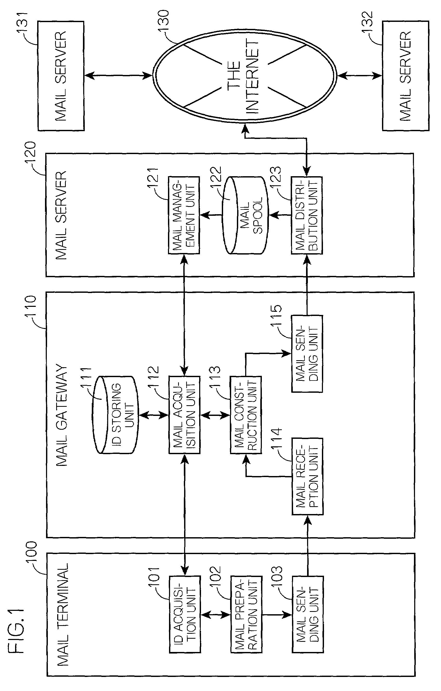
[0137]FIG. 13 is a block diagram showing the construction of the e-mail transmission / reception system according to the second embodiment of the present invention including a mail terminal 140, a mail gateway 150, and a mail server 120.

[0138]FIG. 13 is different from the construction in FIG. 1 in that the mail terminal 140 and the mail gateway 150 are provided as substitutes for the mail terminal 100 and the mail gateway 110, respectively. In the following description, an explanation for the elements which are the same as those in FIG. 1 will be omitted, but elements which are different from those in FIG. 1 will be focused on.

[Different Elements from the Mail Terminal 100]

[0139]As shown in FIG. 13, the mail terminal 140 is different from the mail terminal 100 in that a file format registration unit 141 is further provided.

[0140]The file format registration unit 141 transmits file format conversion information including a receiver's address of the mail and a file form...

Example

Third Embodiment

[0166]FIG. 18 is a block diagram showing the construction of the e-mail transmission / reception system according to the third embodiment of the present invention including a mail terminal 160, a mail gateway 170, and a mail server 120.

[0167]FIG. 18 is different from the construction in FIG. 1 in that the mail terminal 160 and the mail gateway 170 are provided as substitutes for the mail terminal 100 and the mail gateway 110, respectively. In the following description, an explanation for the elements which are the same as those in FIG. 1 will be omitted, but elements which are different from those in FIG. 1 will be focused on.

[Different Elements from the Mail Terminal 100]

[0168]The mail terminal 160 is different from the mail terminal 100 in that a mail preparation unit 162 is provided as a substitute for the mail preparation unit 102.

[0169]The mail preparation unit 162 is different from the mail preparation unit 102 shown in FIG. 1 in that a data format of a field “X-...


PUM


Abstract

A mail gateway generates an identifier for each attached file included in the e-mail addressed to a user and held in a mail server, and notifies a mail terminal belonging to the user of a list of generated IDs. When the user selects attached files that the user wants to attach to the e-mail from the list of IDs that is notified from the mail gateway, the mail gateway constructs e-mail including the selected attached files and the mail server transmits the constructed e-mail to addresses of the receivers of the e-mail.

Description

BACKGROUND OF THE INVENTION[0001](1) Field of the Invention[0002]The present invention relates to an e-mail transmission / reception system. More specifically, the present invention relates to a system for the transmission / reception of e-mail with attached files.[0003](2) Description of the Related Art[0004]The Internet is basically available through terminals provided at offices and homes. Recently, however, new usage patterns of the Internet such as “mobile computing” and “mobile Internet” are becoming common. In the mobile computing, the Internet is accessed by cellular phones and Personal Handyphone Systems (PHS) connected to personal computers or Personal Digital Assistants (PDA). The mobile Internet (e.g., Internet service for cellular phones) refers to a usage pattern that combines mobile machines, which are free from restrictions on time and space, and the Internet, which contains information from all over the world. As the mobile computing and the mobile Internet become wides...

Claims


Application Information

Patent Timeline
IPC IPC(8): G06F15/16H04L12/58
CPCH04L12/58H04L51/08H04L51/216H04L51/56H04L51/00
Inventor KOBAYASHI, SUSUMUOHMURA, TAKESHINAKANISHI, MASANORISUMITA, TETSUJIUEDA, EIJI
Owner PANASONIC CORP
Why Eureka
Try Eureka