Process and apparatus for producing sub-micron fibers, and nonwovens and articles containing same

a technology of sub-micron fibers and processing equipment, which is applied in the direction of spinnerette packs, weaving, manufacturing tools, etc., can solve the problems of low defect fibers, difficult production of cost-effective sub-micron fibers, and high production costs of conventional spunmelt equipment arrangements, so as to reduce gas demand, reduce energy consumption, and increase the output of sub-micron fibers

Inactive Publication Date: 2010-02-23
AVINTIV SPECIALTY MATERIALS INC
View PDF24 Cites 95 Cited by
  • Summary
  • Abstract
  • Description
  • Claims
  • Application Information

AI Technical Summary

Benefits of technology

[0015]As another advantage of the present invention, increased sub-micron fiber output is obtained with lower gas demand. Lowered gas demand makes it possible to reduce energy consumption and / or use smaller scale unit operations to still provide commercially significant sub-micron fiber output levels. In one embodiment, the gas stream and polymer fluid stream are introduced into the second section at a gas stream / polymer fluid stream mass flow rate ratio less than about 40:1, particularly less than about 30:1; more particularly less than about 15:1. The gas stream to polymer fluid stream mass flow ratio is calculated as kilogram per hour per meter of gas stream through the gas passage to kilogram per hour per meter of polymer fluid stream through all the polymer openings in the second section of the gas passage.
[0016]In more particular embodiments, each polymer passage opening may be a slit with a hydraulic diameter defined as four times cross-sectional area of the polymer passage opening divided by inner perimeter of the polymer passage opening, said hydraulic diameter of each polymer passage opening ranging from about 0.001 inch to about 0.100 inch. The polymer film generally has a polymer film thickness not exceeding the hydraulic diameter of the polymer passage opening. The polymer fluid may expand upon exiting the polymer passage opening, for example, due to die swell phenomenon without being limited by theory. However, the polymer fluid film thickness almost instantaneously becomes lesser than or equal to the hydraulic diameter of the polymer passage opening.
[0017]In characterizing the geometry of the wall-defined gas passage of the nozzle of the present invention, a first bisecting surface, defined as an angular bisector of the angle between the first and second walls in the first section, geometrically divides the first section into two halves with about equal volumes, and a second bisecting surface, defined as an angular bisector of the angle between the first and second walls in the second section, geometrically divides the second section into two halves with about equal volumes. The bisecting surface may be planar or curvilinear, depending on the embodiment of the present invention, as will be more apparent from the detailed descriptions herein. In a general embodiment, the bisection angle of the first and the second walls with respect to the first bisecting surface ranges from about 15 to about 40 degrees in the first section, and the bisection angle of the first and the second walls with respect to the second bisecting surface ranges from about 2 to about 20 degrees in the second section of the gas passage.
[0018]The opposing walls of nozzle where polymer is introduced into the gas passage may be operated such that they are thermally similar or different. In one embodiment, the first and second walls of the gas passage are heated to approximately the same temperature to provide symmetric thermal states with respect to the first and the second bisecting surfaces. In an alternative embodiment, one of the opposing walls may be a hot wall while the other wall is a cold wall, wherein temperature of the hot wall is at least higher than the cold wall, such as at least 50° C. higher, and only the hot wall has at least one polymer fluid passage opening. In this configuration, the microfibers may be produced in a hot melt / “cold” gas (e.g., unheated air) fibrillation environment that reduces process complexity and costs. In this embodiment, the hot wall in the second section diverges away from the first bisecting surface at an angle that ranges from about 1 degree to 20 degrees, and the cold wall in the second section converges towards the first bisecting surface at an angle that ranges from about 0.1 degree to about 15 degrees. The ratio between the diverging angle of the hot wall relative to the first bisecting surface and the converging angle of the cold wall relative to the first bisecting surface may range from about 1:1 to about 500:1. The angle between centerline of each polymer passage and the wall containing the corresponding polymer passage opening may range from about 10 degrees to about 100 degrees. The polymer film extruding from each polymer passage opening may flow with the gas flow along a polymer fiberization surface, which has an orientation angle with respect to the first bisecting surface ranging from about 90 degrees measured in clockwise direction to about 45 degrees measured in counterclockwise direction. The length of the polymer fiberization surface corresponding to each polymer passage opening may be less than about one thousand times the hydraulic diameter of the corresponding polymer passage opening.
[0019]In another embodiment, the first and second walls of the gas passage are smoothly curved such that the curvature of the opposing walls in the first section smoothly transitions without any sharp edges into the curvature of the opposing walls in the second section in the region of smallest cross-section area of the gas passage. The opposing walls in the second section of the gas passage may be curved such that the hot wall has a convex shape that curves away from the second bisecting surface and the cold wall has a concave shape that curves towards the second bisecting surface as viewed from within the second section in the gas passage. The ratio of the radius of curvature of the hot wall to the radius of curvature of the cold wall in the second section of the gas passage ranges from about 1:10,000 to about 100:1. The gas stream is introduced into the gas passage at a mass flow rate ranging from about 150 kilogram per hour per meter to about 3500 kilogram per hour per meter.
[0020]The nozzle used in the processes described herein for making nonwoven webs comprising sub-micron fibers represents another embodiment of the present invention. The inventive nozzle device is not limited to any particular type of polymer material or fibrillating gas and allows for the polymer to be independently selected for a specific application from amongst a wide variety of polymeric materials. Particularly the fibrillating gas is a gaseous material such as air, nitrogen, steam, etc. The gas may be used as a single type thereof or as combinations of different gases. Additionally suitable gases may include reactive gases or gases with reactive components, or combinations thereof. In embodiments, the gas generally may be inert to the nozzle wall materials. For purposes herein, the terms “nozzle system” and “nozzle” are used interchangeably.

Problems solved by technology

Although several methods have been used, there are drawbacks to each of the methods and producing cost effective sub-micron fibers has been difficult.
Conventional spunmelt equipment arrangements can not provide high quality, low defect fibers and webs that are predominantly microfine including submicron diameter fibers with narrow fiber size distributions.
The production rates of this process are very slow and fibers are typically produced in small quantities.
They generally use concentric input and channeling of gas and polymer melt in the discharge nozzles, which can be non-optimal from standpoints of equipment lay-out complexity and equipment maintenance, etc.
However, other nozzle configurations, such as non-concentric (non-annular) layouts of nozzles pose challenges of their own.
For instance, in a fiber or filament nozzle system where polymer melt and gas introduction proceed from separate side-by-side units, a problem tends to arise when the fiberization gas flows between a side with a surface or wall that is heated to a high temperature (e.g., due to polymer melt flow introduction from that side) and a surface or wall of an opposing side (for example, an gas introduction side) that is at a lower temperature than the polymer melt side.
In such a scenario, gas flow tends to become unstable in the diverging section in prior nozzle configurations such as with a Laval nozzle.
This leads to problems of lack of polymer shear, polymer back-flow or build-up into the gas side of the gas passage, and subsequently an unevenly varying excessive and diminishing polymer flow and fiberization.
After sufficient melt build up occurs upstream into the gas side, polymer melt separates and is typically blown out as a “shot,” since the melt locally cools down and can no longer form fibers due to insufficient shearing of polymer.
When the polymer flow starves as the other end of those variation, the shearing is excessive leading to undesired dust.

Method used


Image

  • Process and apparatus for producing sub-micron fibers, and nonwovens and articles containing same
  • Process and apparatus for producing sub-micron fibers, and nonwovens and articles containing same
  • Process and apparatus for producing sub-micron fibers, and nonwovens and articles containing same

Examples


example

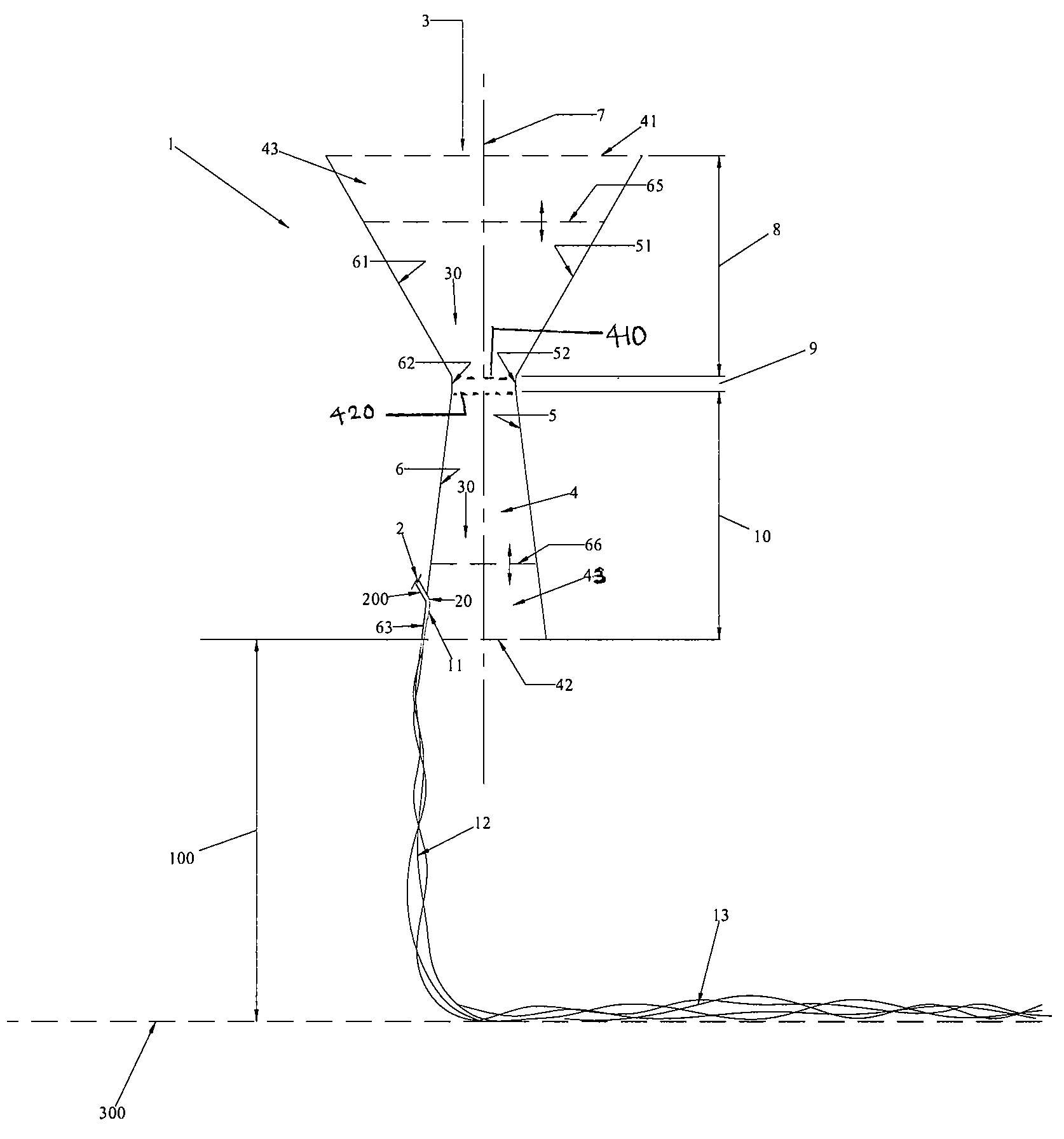
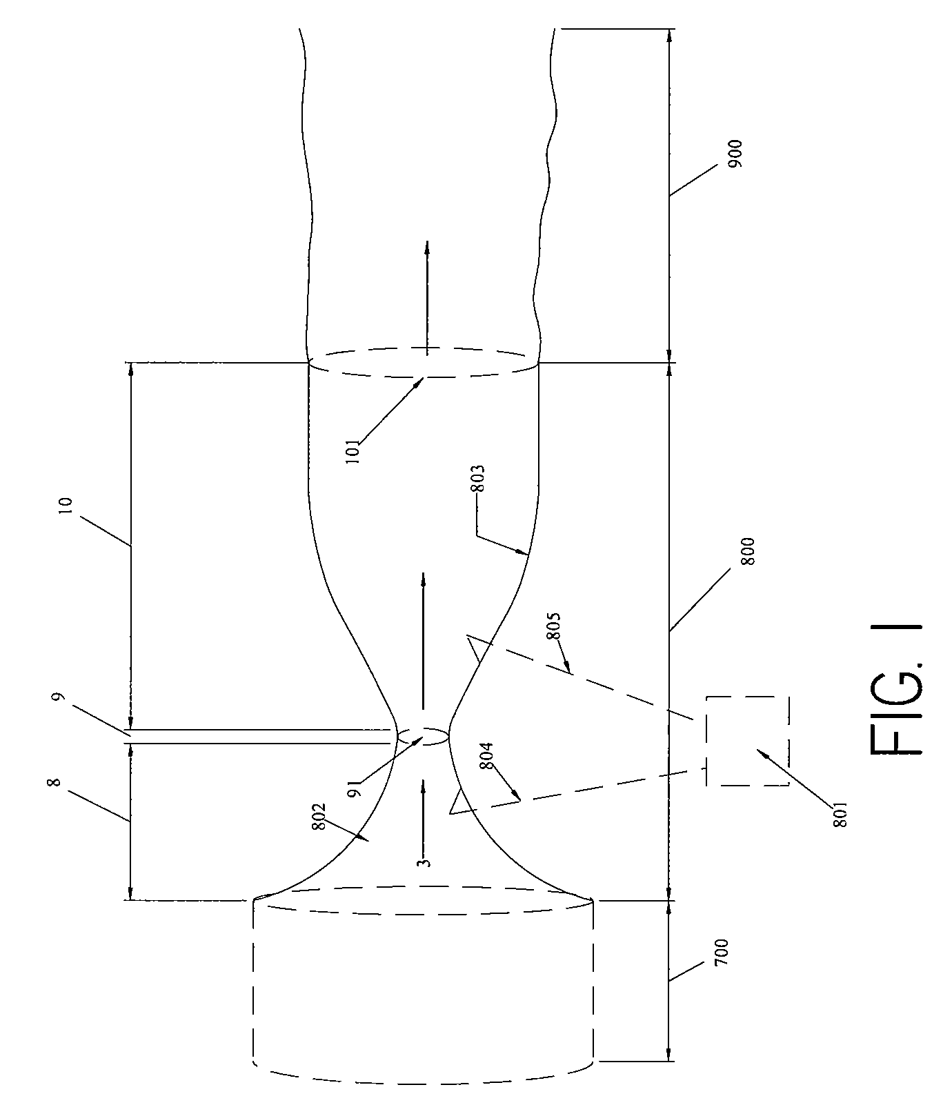
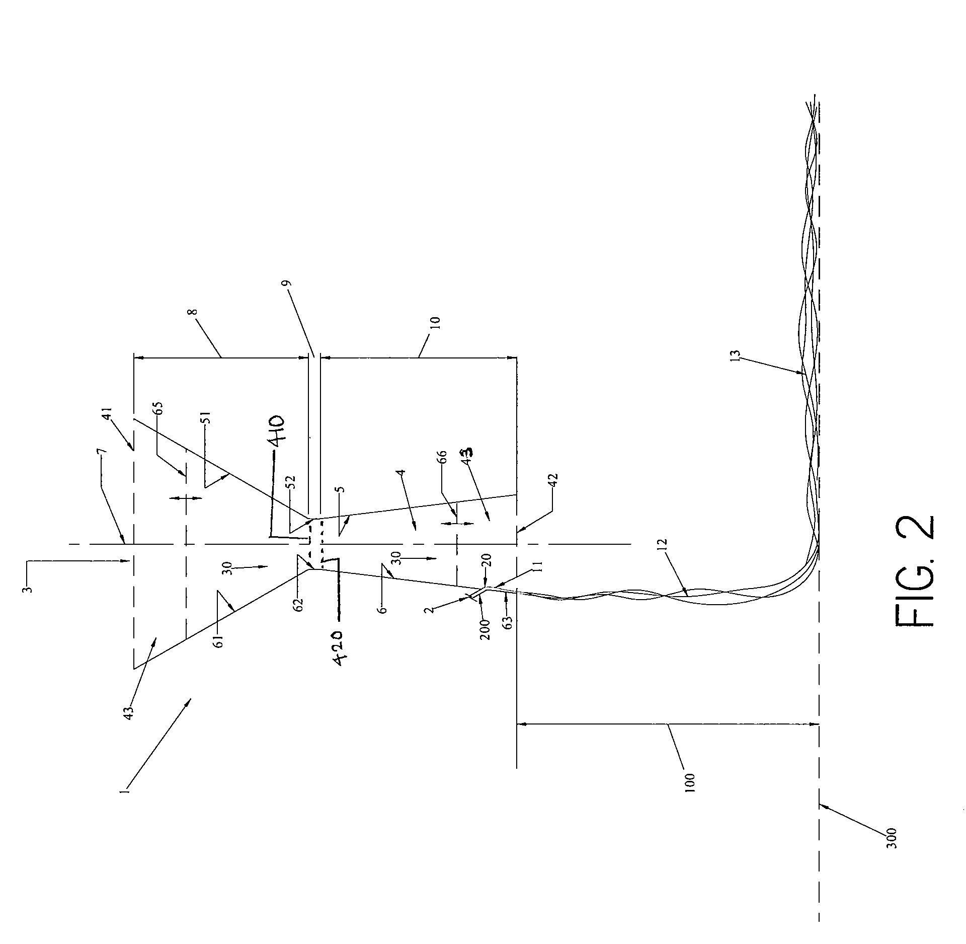
[0068]An extruder (2.5 inch diameter, single screw extruder) and a conventional melt blown die body (25 inch width) were used to provide a source of 1800 MFR polypropylene. The extruder temperature was 650° F. A nozzle generally having the configuration of FIG. 4 was mounted to a conventional extruder die body using a conventional gasketed bolt mount at an upper flat surface region on the nozzle device. A source of pressurized air was fed from an air supply to the inlet of the nozzle via air-tight connections and seals. The nozzle had the following geometrical features (using FIG. 4 as a non-limiting example): an 0.016 inch as the minimum distance between opposing walls 5 and 6 in the throat section 9; cold wall 5 converging at an angle θ of negative 1.5 degrees towards the bisecting plane 7; hot wall diverging away at an angle β of 2 degrees from the bisecting plane 7; the polymer passage entered the second section in the second, downstream half of the second section and had a hydr...


PUM

PropertyMeasurementUnit
temperatureaaaaaaaaaa
diameter distributionaaaaaaaaaa

Abstract

A process and apparatus for producing sub-micron fibers, and more specifically a process and apparatus for effecting formation of sub-micron fibers by fibrillation of polymer films, and nonwoven materials and articles incorporating them.

Description

TECHNICAL FIELD[0001]The present invention generally relates to producing sub-micron fibers, and more specifically relates to a process and apparatus for effecting formation of sub-micron fibers by fibrillation of polymer films, and nonwoven materials and articles incorporating them.BACKGROUND ART[0002]Continuous and discontinuous filament spinning technologies are known in art, and are commonly referred to as spunmelt technologies. Spunmelt technologies include both the meltblown or spunbond processes. A spunbond process involves supplying a molten polymer, which is then extruded under pressure through a large number of orifices in a plate known as a spinneret or die. The resulting continuous filaments are quenched and drawn by any of a number of methods, such as slot draw systems, attenuator guns, or Godet rolls. The continuous filaments are collected as a loose web upon a moving foraminous surface, such as a wire mesh conveyor belt. When more than one spinneret is used in line fo...

Claims


Application Information

Patent Timeline
Patent Type & Authority Patents(United States)
IPC IPC(8): B29C39/14B29D99/00
CPCD01D4/025D04H1/565D01D5/423Y10S428/903D04H1/56B29C48/865D04H3/16Y10T442/626Y10T442/614Y10T442/609Y10T442/68Y10T442/66D04H13/02D04H1/4382
Inventor JOHNSON, MICHAEL H.KRAUSE, TIMOTHYHAYES, MICHAEL W.CHHABRA, RAJEEVAYDORE, SAVASISELE, OLAF ERIK ALEXANDERXU, HAN
Owner AVINTIV SPECIALTY MATERIALS INC
Why Eureka
Try Eureka