Hydrogen production system using wind turbine generator

a technology of wind turbine generator and hydrogen production system, which is applied in the direction of machines/engines, proportional-integral algorithms, electric generator control, etc., can solve the problems of increasing the amount of hydrogen produced by the hydrogen production system, and achieves the reduction of wind turbine rotational speed variations, prolonging time, and reducing rotational speed variations

Inactive Publication Date: 2010-02-23
HITACHI LTD
View PDF22 Cites 12 Cited by
  • Summary
  • Abstract
  • Description
  • Claims
  • Application Information

AI Technical Summary

Benefits of technology

[0010]It is an object of the present invention to provide a hydrogen production system which uses a wind turbine and which controls a power converter system in such a way that the wind turbine stays in its operable range for a longer time to thereby produce hydrogen for a longer time.
[0011]The amount of electrical current supplied to the electrolytic hydrogen production system is varied according to the rotational speed of the wind turbine, thus reducing variations in the rotational speed. Furthermore, the pitch angle of the wind turbine is varied according to the rotational speed. This reduces variations in the rotational speed of the wind turbine. A permanent-magnet generator is used as an electricity generator for the wind turbine to derive a power supply during start-up. Alternatively, a power storage system is used as an assisting device at start-up or only a power supply for control is supplied from the system.
[0012]In the wind turbine-driven hydrogen production system according to the present invention, the wind turbine stays in its operable range in a longer time. The wind turbine is stopped less frequently than conventional. Consequently, hydrogen is produced for a longer time. This increases the amount of hydrogen produced by the hydrogen production system.

Problems solved by technology

This increases the amount of hydrogen produced by the hydrogen production system.

Method used


Image

  • Hydrogen production system using wind turbine generator
  • Hydrogen production system using wind turbine generator
  • Hydrogen production system using wind turbine generator

Examples


embodiment 1

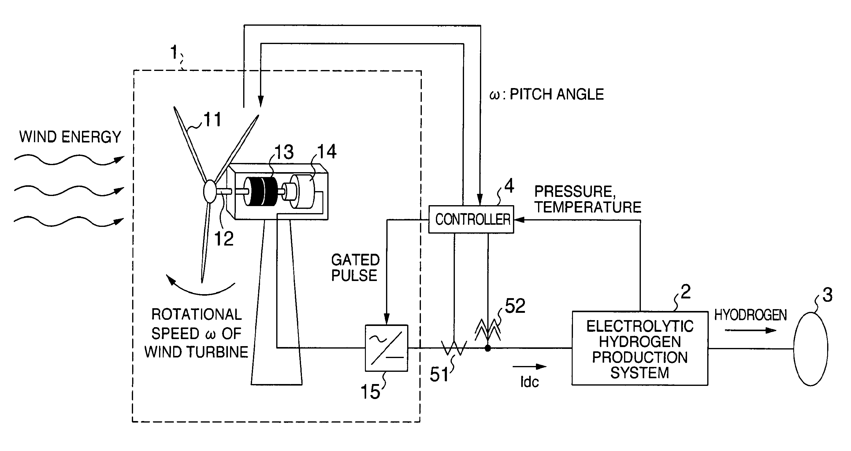
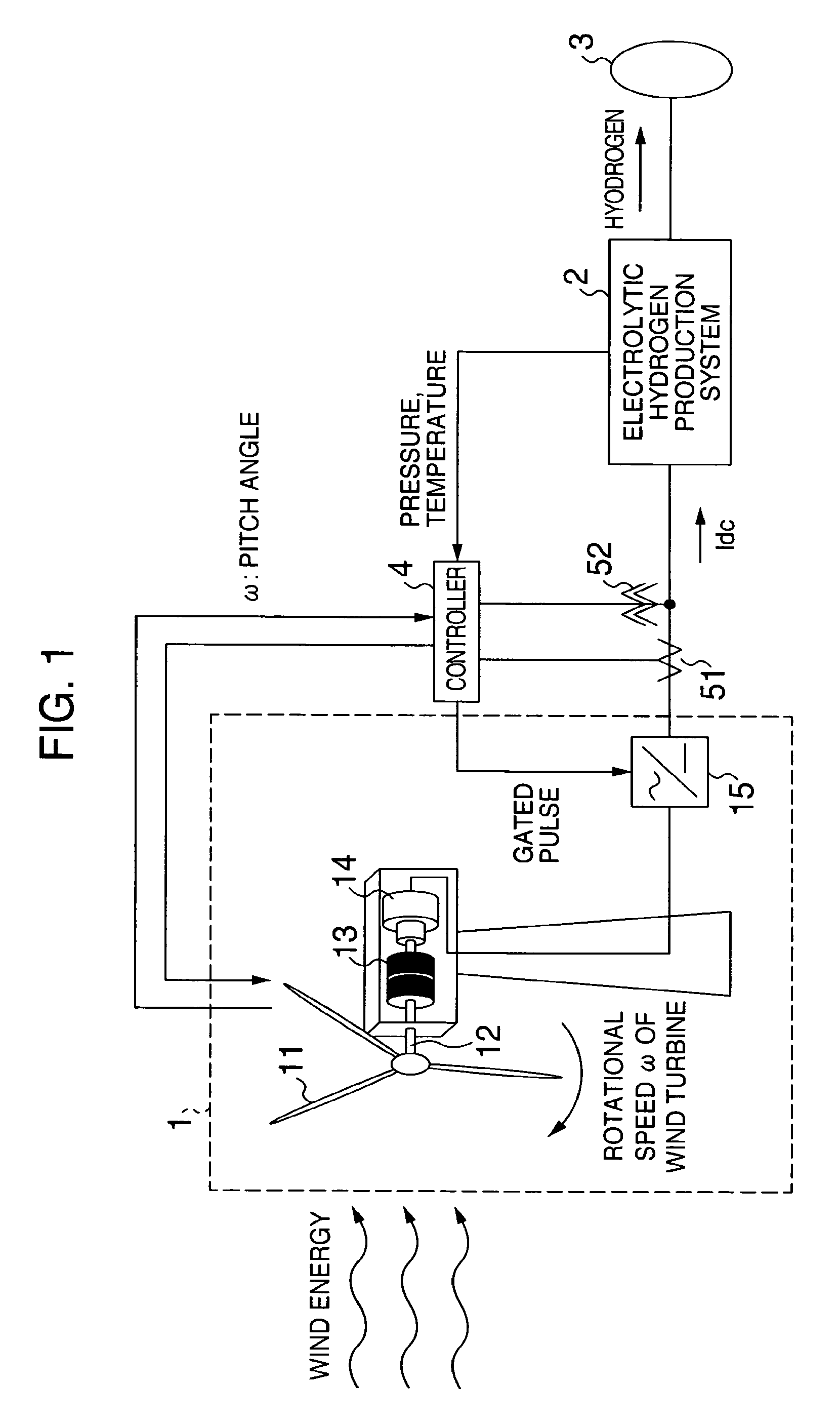
[0029]FIG. 1 shows the configuration of a wind turbine-driven hydrogen production system according to an embodiment of the present invention. The wind turbine, indicated by reference numeral 1, has blades 11 catching wind, and acts to convert the wind energy into rotary energy. The blades 11 are connected to an electricity generator 14 via gears 13. The gears 13 convert the rotational speed of the blades 11 into a rotational speed adapted for the generator 14. A permanent-magnet generator, induction generator, synchronous generator, doubly-fed induction generator, or the like can be used as the generator 14. The rotary energy of the blades 11 is converted into electrical energy by the generator 14 and then transferred to a power converter system 15.

[0030]A controller 4 receives signals indicating the temperature of an electrolytic hydrogen production system 2, the pressure of the hydrogen, and the rotational speed ω of the wind turbine 1, and creates a command value Idc* of the elec...

embodiment 2

[0046]The present embodiment is described. The present embodiment pertains to self-starting of a hydrogen production system using a wind turbine. First, the prior-art method of starting the wind turbine connected with an electric power system is described. The main circuit portions of the wind turbine are connected with the electric power system via a converter and an inverter. The main circuit portions are circuits which are connected from the output terminal of the electricity generator to the system via a power converter system. A circuit breaker is present within the power converter system of the wind turbine. When the wind turbine is at stand-by state, the main circuit is electrically disconnected from the power system. On the other hand, the power supply for the controllers of the wind turbine is supplied from the power system using a step-down transformer. Therefore, if the generator is at rest, the control power supply is supplied and so the converter can be controlled. When...

embodiment 3

[0050]The present embodiment pertains to self-starting of a hydrogen production system using a wind turbine. The difference of the present embodiment with Embodiment 1 is that the generator of the wind turbine needs an exciter.

[0051]First, the prior-art method of starting a wind turbine which needs an exciter and is connected with an electric power system is described. An example of a generator that needs an exciter is a doubly-fed induction generator. The stator of the doubly-fed induction generator is directly connected to the electric power system. An excitation current is supplied to the rotor from a converter. A power supply for the controller is supplied from the electrical power system via a step-down transformer. The controller waits using the power supply supplied from the power system until the wind turbine assumes an operable state. When the operable state is reached, the inverter and converter are operated. An excitation current is supplied to the stator side of the gene...


PUM


Abstract

A wind turbine-driven hydrogen production system controlling a power converter system such that the wind turbine stays in its operable range for a longer time and thus the hydrogen production system produces hydrogen for a longer time. The wind turbine-driven hydrogen production system varies an amount of electrical current supplied to an electrolytic hydrogen production system according to the rotational speed of the wind turbine to reduce variations in the rotational speed. Furthermore, the pitch angle of the wind turbine varies according to the speed. Thus, variations in the speed of the wind turbine can be reduced. A permanent-magnet generator is used as the electricity generator of the wind turbine to obtain a power supply at start-up. Alternatively, a power storage system used as assistive equipment at start-up is supplementarily added or only a power supply for the controllers is supplied from a system.

Description

CROSS REFERENCE TO RELATED APPLICATION[0001]The present application claims priority from Japanese application JP2006-068915 filed on Mar. 14, 2006, the content of which is incorporated by reference herein.BACKGROUND OF THE INVENTION[0002]The present invention relates to a wind turbine-driven hydrogen production system for producing hydrogen by supplying electric power generated by a wind turbine to an electrolytic hydrogen production system and, more particularly, to a wind turbine-driven hydrogen production system which includes the wind turbine whose main circuit portions are mounted independent of a power system.[0003]Today, most of energies sustaining our life are supplied from fossil fuels. However, there is the problem that the resources will be exhausted. In addition, there is the problem of environmental crises such as global warming. One conceivable method of solving these problems is to exploit a renewable energy such as wind power, solar energy, or water power.[0004]Renew...

Claims


Application Information

Patent Timeline
Patent Type & Authority Patents(United States)
IPC IPC(8): F03D9/00H02P9/00
CPCC25B15/02F03D7/0244F03D7/0272F03D7/0276F03D7/042F03D9/00H02P9/00H02P9/08F03D7/0224H02P2101/15F05B2220/61F05B2220/7068F05B2270/705Y02E10/723Y02E10/725Y02E70/10F03D7/026Y02P20/133F03D9/25Y02E10/72Y02E60/36
Inventor OOHARA, SHINYAICHINOSE, MASAYAFUTAMI, MOTOOMATSUTAKE, MITSUGUFUJII, KAZUMIIDE, KAZUMASAITABASHI, TAKEYUKITAMURA, JUNJI
Owner HITACHI LTD
Why Eureka
Try Eureka