Methods for achieving improved color in microencapsulated electrophoretic devices

a micro-encapsulated electrophoretic and color technology, applied in the field of full-color electrophoretic displays, can solve the problems of unsatisfactory color display, lack of efficient and inexpensive manufacturing methods, and failure to commercialize full-color electrophoretic displays, and achieve the effect of efficient and cheap manufacture of full-color encapsulated electrophoretic displays and inexpensive display itsel

Inactive Publication Date: 2010-02-23
E INK CORPORATION
View PDF270 Cites 240 Cited by
  • Summary
  • Abstract
  • Description
  • Claims
  • Application Information

AI Technical Summary

Benefits of technology

[0007]This invention teaches practical ways to efficiently and cheaply manufacture full-color, encapsulated electrophoretic displays. In one embodiment the display media can be printed and, therefore the display itself can be made inexpensively.

Problems solved by technology

While bichromatic electrophoretic displays have been demonstrated in a limited range of colors (e.g. black / white or yellow / red), to date there has not been successful commercialization of a full-color electrophoretic display.
One reason for this failure of commercialization is the lack of a method of manufacture that is efficient and inexpensive.
Failure to achieve either substantially equal proportions of colored display elements or failure to achieve-registration of the display elements with the addressing electrodes results in a color display that is unsatisfactory.

Method used


Image

  • Methods for achieving improved color in microencapsulated electrophoretic devices
  • Methods for achieving improved color in microencapsulated electrophoretic devices
  • Methods for achieving improved color in microencapsulated electrophoretic devices

Examples


Embodiment Construction

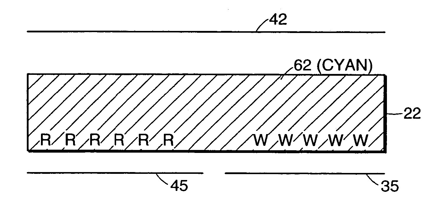
[0043]Electronic ink is an optoelectronically active material that comprises at least two phases: an electrophoretic contrast media phase and a coating / binding phase. The electrophoretic phase comprises, in some embodiments, a single species of electrophoretic particles dispersed in a clear or dyed medium, or more than one species of electrophoretic particles having distinct physical and electrical characteristics dispersed in a clear or dyed medium. In some embodiments the electrophoretic phase is encapsulated, that is, there is a capsule wall phase between the two phases. The coating / binding phase includes, in one embodiment, a polymer matrix that surrounds the electrophoretic phase. In this embodiment, the polymer in the polymeric binder is capable of being dried, crosslinked, or otherwise cured as in traditional inks, and therefore a printing process can be used to deposit the electronic ink onto a substrate.

[0044]In one embodiment, the ink may comprise display elements capable ...


PUM

PropertyMeasurementUnit
diametersaaaaaaaaaa
dielectric constantaaaaaaaaaa
specific gravityaaaaaaaaaa

Abstract

A method for manufacturing a full color, reflective display includes the steps of depositing a first plurality of electrophoretic display elements in substantial registration with a first electrode and a second plurality of electrophoretic display elements in substantial registration with a second electrode. The electrophoretic display elements include a capsule containing a species of particles dispersed in a suspending fluid. The selective deposition of the display elements can be achieved by ink-jet printing methods, screen printing methods or other printing methods. In some embodiments the electrodes are printed onto the substrate before selective deposition of the display elements, while in other embodiments the substrate is provided having the electrodes already disposed on it. In still other embodiments, the sequence of printing of electrodes and electrophoretic display elements can be varied.

Description

CROSS-REFERENCE TO RELATED APPLICATIONS[0001]This application is a continuation of prior application Ser. No. 09 / 349,806, filed on Jul. 8, 1999, which in turn claims priority to U.S. Ser. No. 60 / 092,050 filed Jul. 8, 1998, the contents of both being incorporated herein by reference.FIELD OF THE INVENTION[0002]The present invention relates to electronic displays and, in particular, to full color electrophoretic displays and methods of manufacturing full-color microencapsulated electrophoretic displays.BACKGROUND OF THE INVENTION[0003]Electrophoretic display media are generally characterized by the movement of particles through an applied electric field. These displays are highly reflective, can be made bistable, can be scaled to large areas, and consume very little power. These properties allow encapsulated electrophoretic display media to be used in many applications for which traditional electronic displays are not suitable. While bichromatic electrophoretic displays have been demo...

Claims


Application Information

Patent Timeline
Patent Type & Authority Patents(United States)
IPC IPC(8): G09G3/34B41J3/407G02B26/02G02F1/1333G02F1/1334G02F1/167G02F1/16757G09F9/302G09F9/37H01L27/28H01L51/00H01L51/05H01L51/30
CPCB41J3/4073B41J3/4076G02B26/026G09F9/302G09F9/372H01L27/28G02F1/133305G02F1/1334G02F1/167G02F2202/28H01L51/005H01L51/0077H01L51/0512B41J2/2117G02F1/16757H10K85/60H10K85/30H10K10/462B05D5/06H10K19/00
Inventor JACOBSON, JOSEPH M.MORRISON, IAN D.WILCOX, RUSSELL J.DRZAIC, PAUL
Owner E INK CORPORATION
Why Eureka
Try Eureka