System and method for assessing virtual slide image quality

a virtual slide and image quality technology, applied in the field of virtual microscopy, can solve the problems of difficult to accurately assess the image quality of the virtual slide, the perimeter area of the image tile is out of focus, and the limitations of conventional image tiling solutions, so as to increase the likelihood of time-consuming re-scans and increase the likelihood of re-scans

Inactive Publication Date: 2010-02-23
LEICA BIOSYST IMAGING
View PDF56 Cites 94 Cited by
  • Summary
  • Abstract
  • Description
  • Claims
  • Application Information

AI Technical Summary

Benefits of technology

[0014]Alternatively, the assessment can be done in real time during the scanning process. This allows focus points that have a distance from the best fit surface that exceeds the predetermined maximum value to be identified and discarded or recalibrated prior to the image capture process in order to increase the likelihood that all of the imagery data captured during the scanning of a virtual microscope slide image is in sharp focus and also to increase the likelihood that time consuming re-scans will be unnecessary.
[0015]Furthermore, when a set of slides are automatically scanned in succession, a resulting graphical display can be presented that identifies the slides in a fashion that easily demonstrates to an operator the virtual slide images that need manual inspection. This also identifies for the operator the physical microscope slides that may need to be re-scanned. The graphical display may also provide the operator with easy access to viewing a designated virtual slide image so that the manual inspection process is streamlined. The graphical display may also provide the operator with easy access to a re-scan mode so that the re-scanning process is also streamlined.

Problems solved by technology

An image tiling system is restricted to a single focus height for each individual snapshot taken by its camera, thus, each of these “fields of view” have areas that are out of focus when the subject specimen being scanned does not have a uniform surface.
Moreover, conventional image tiling systems suffer from circular optical distortion that is inherent in the use of an area scan camera with an objective lens.
This circular distortion causes the perimeter area of an image tile to be out of focus.
Conventional image tiling solutions are severely handicapped by these limitations, with their only recourse for the inherent circular optical distortion being to discard a significant amount of out of focus image data on the perimeter of each image tile.
Furthermore, even when the out of focus perimeter image data is discarded, the remaining image data still suffers from out of focus areas on each image tile due to the lack of a uniform surface and also from circular optical distortion.
Although the imagery data captured by a line scan camera is objectively better, there are still focus problems that may arise during image capture.
Additionally, when a tissue specimen does not lay flat on the glass (often referred to as having “folded” tissue) the field of view (“FOV”) of the objective lens cannot be brought into focus using a single focus height.
Also, in some cases the tissue specimen does not have sufficient contrast to allow the pre-scan focus procedure to make an accurate measurement.
Finally, a microscope slide may not be held securely during the scanning process.
If this occurs, the height of the slide will likely change during the scanning process, after which the focus points identified in the pre-scan focus procedure will no longer be valid.
However, identifying virtual slide images with out of focus areas requires a manual inspection of each virtual slide image.
This is a very costly and time consuming quality control problem.
And when out of focus virtual slide images are detected, an operator must use a manual procedure to re-scan the virtual slide image, which is also time consuming.

Method used


Image

  • System and method for assessing virtual slide image quality
  • System and method for assessing virtual slide image quality
  • System and method for assessing virtual slide image quality

Examples


Embodiment Construction

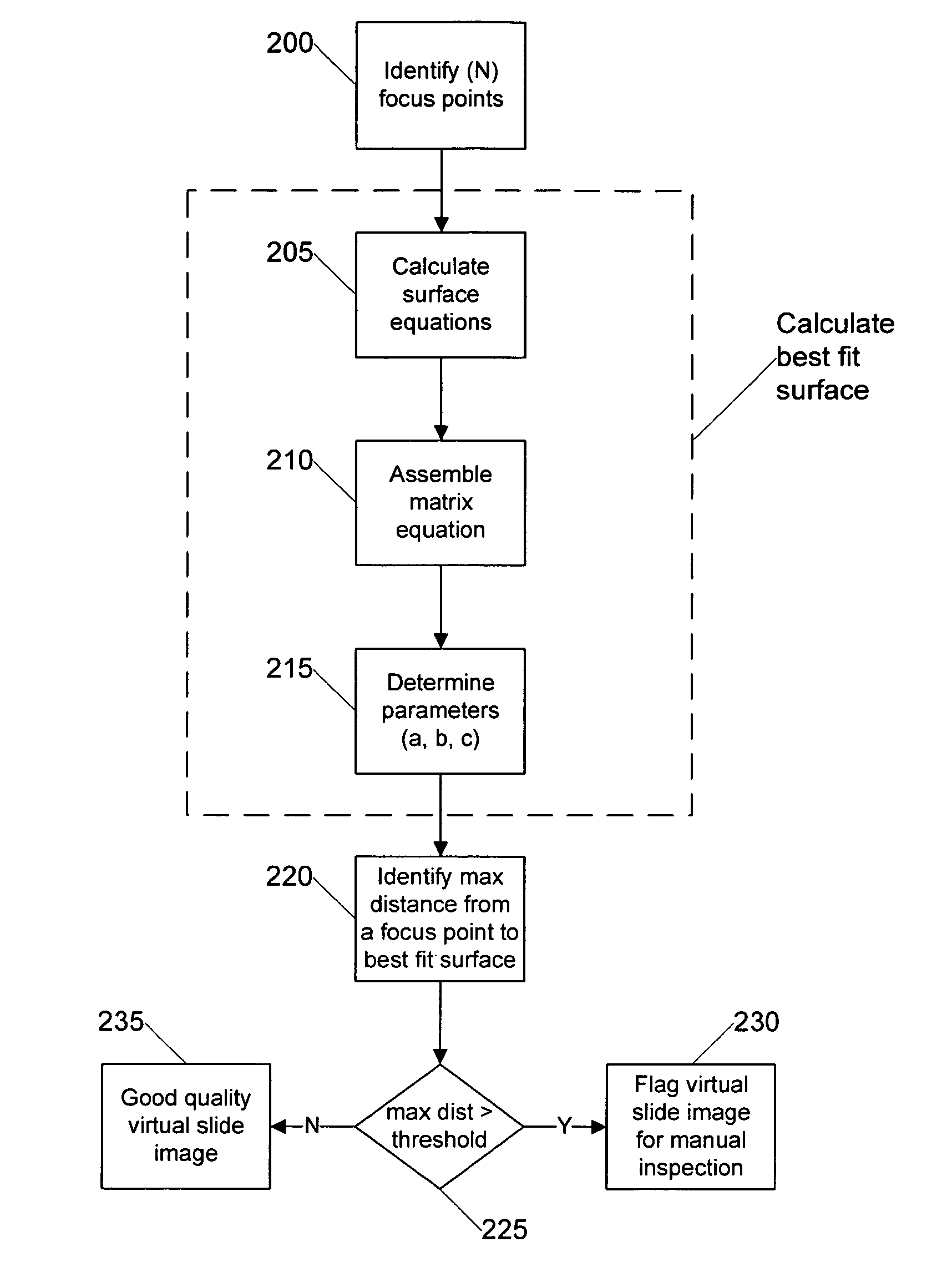
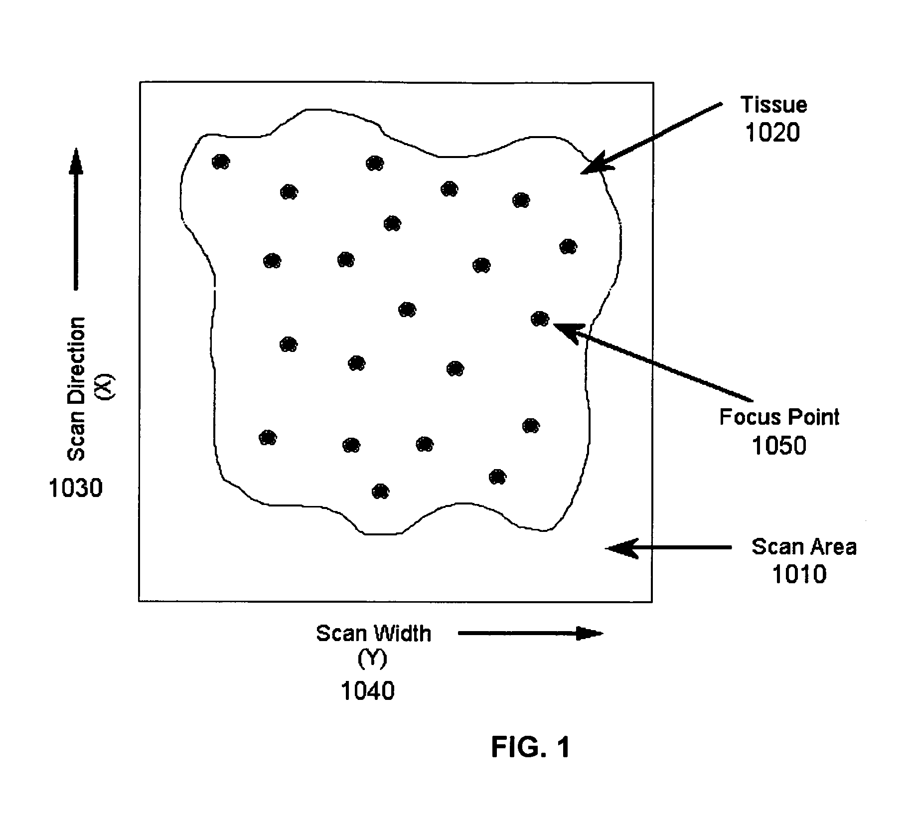
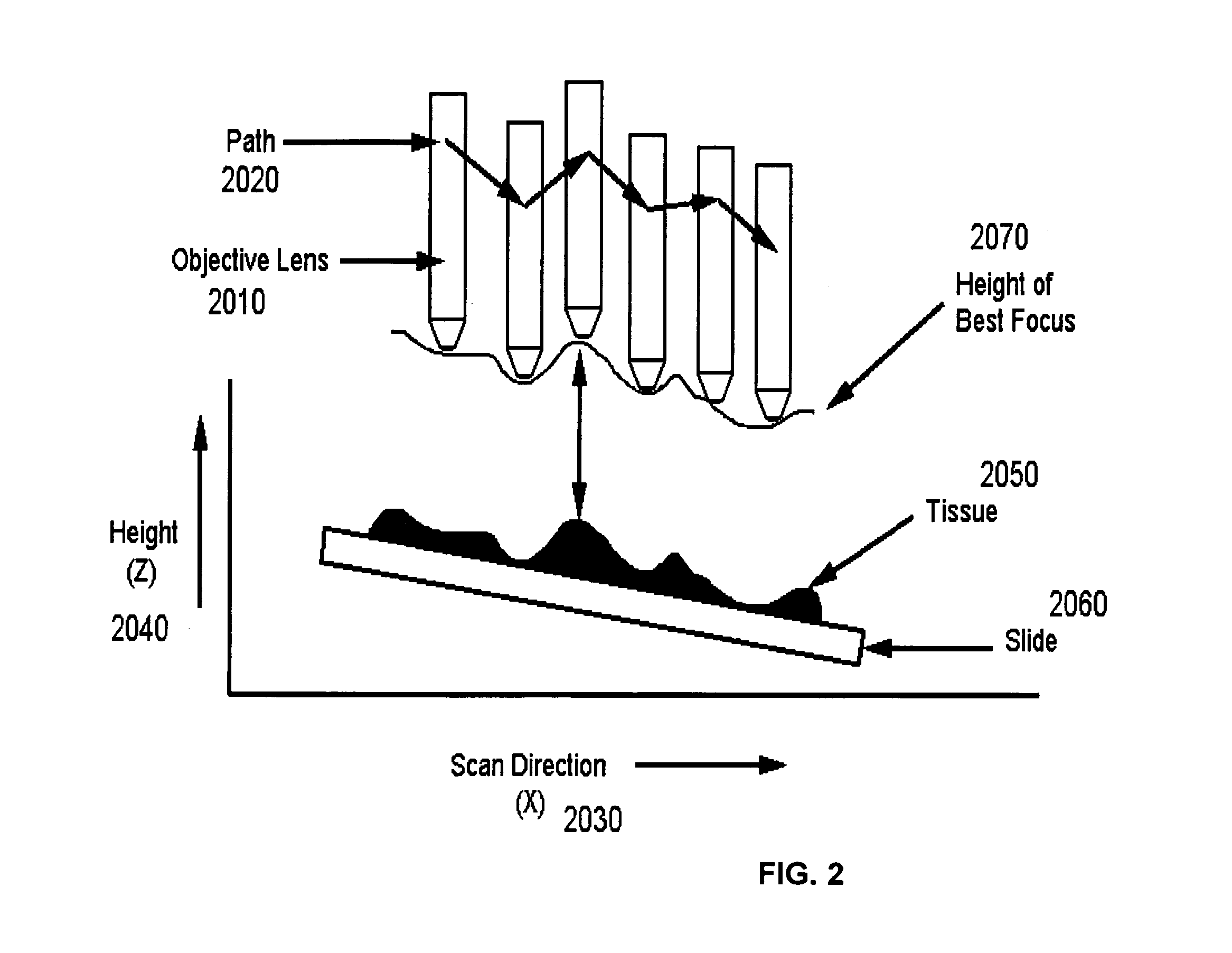
[0025]Certain embodiments as disclosed herein provide for systems and methods for assessing virtual microscope slide image quality to determine whether a virtual slide image has any out of focus areas and is therefore a candidate for manual inspection. For example, one method as disclosed herein allows for the various focus points used to scan the virtual slide image to be used in calculating a best fit surface for the virtual slide image. The distance of each focus point from the best fit surface is then calculated and the largest distance is compared to a predetermined value. If the largest distance from a focus point to the best fit surface is larger than the predetermined value, then the virtual slide image is designated as needing a manual inspection and possible re-scan.

[0026]After reading this description it will become apparent to one skilled in the art how to implement the invention in various alternative embodiments and alternative applications. However, although various e...


PUM


Abstract

Systems and methods for assessing virtual microscope slide image quality are provided. In order to determine whether a virtual slide image has any out of focus areas and is therefore a candidate for manual inspection, the various focus points used to scan the virtual slide image are used to calculate a best fit surface for the virtual slide image. The distance of each focus point from the best fit surface is then calculated and the largest distance is compared to a predetermined value. If the largest distance from a focus point to the best fit surface is larger than the predetermined value, then the virtual slide image is designated as needing a manual inspection and possible re-scan.

Description

RELATED APPLICATION[0001]The present application claims the benefit of U.S. provisional patent application Ser. No. 60 / 575,047 filed on May 27, 2004 and is a continuation-in-part of U.S. patent application Ser. No. 10 / 827,207 filed on Apr. 16, 2004, now U.S. Pat. No. 7,518,652, and is a continuation-in-part of U.S. patent application Ser. No. 10 / 798,457 filed on Mar. 11, 2004, now U.S. Pat. No. 6,917,696, which is a continuation of U.S. patent application Ser. No. 09 / 563,437, filed May 3, 2000, now U.S. Pat. No. 6,711,283. Each of the aforementioned pending applications is incorporated herein by reference in its entirety.BACKGROUND[0002]1. Field of the Invention[0003]The present invention relates to the field of virtual microscopy and more particularly relates to the assessment of image quality based upon the focus map of a line scan camera prior to and during the capture of imagery data from a specimen on a microscope slide.[0004]2. Related Art[0005]In conventional virtual microsco...

Claims


Application Information

Patent Timeline
Patent Type & Authority Patents(United States)
IPC IPC(8): G06K9/00
CPCG02B21/002G02B21/244H04N5/23212G02B21/367G02B21/245G02B21/365H04N23/67
Inventor OLSON, ALLENSALIGRAMA, KIRANSOENKSEN, DIRK G.
Owner LEICA BIOSYST IMAGING
Why Eureka
Try Eureka