Data bus inversion detection mechanism

a data bus and inversion detection technology, applied in the field of microelectronics, can solve the problems of adding latency to the time required to evaluate a given set of inputs, and the operation of counting the number of bits that will change is not so simpl

Active Publication Date: 2010-02-23
VIA TECH INC
View PDF14 Cites 5 Cited by
  • Summary
  • Abstract
  • Description
  • Claims
  • Application Information

AI Technical Summary

Problems solved by technology

While determining which of the bits that will change is simple from a circuit design perspective, the operation of counting the number of bits that will change is not so simple.
Consequently, any additional gate delays that are required to evaluate a given set of inputs adds latency to the time required to evaluate a given set of inputs.

Method used


Image

  • Data bus inversion detection mechanism
  • Data bus inversion detection mechanism
  • Data bus inversion detection mechanism

Examples


Embodiment Construction

[0027]The following description is presented to enable one of ordinary skill in the art to make and use the present invention as provided within the context of a particular application and its requirements. Various modifications to the preferred embodiment will, however, be apparent to one skilled in the art, and the general principles defined herein may be applied to other embodiments. Therefore, the present invention is not intended to be limited to the particular embodiments shown and described herein, but is to be accorded the widest scope consistent with the principles and novel features herein disclosed.

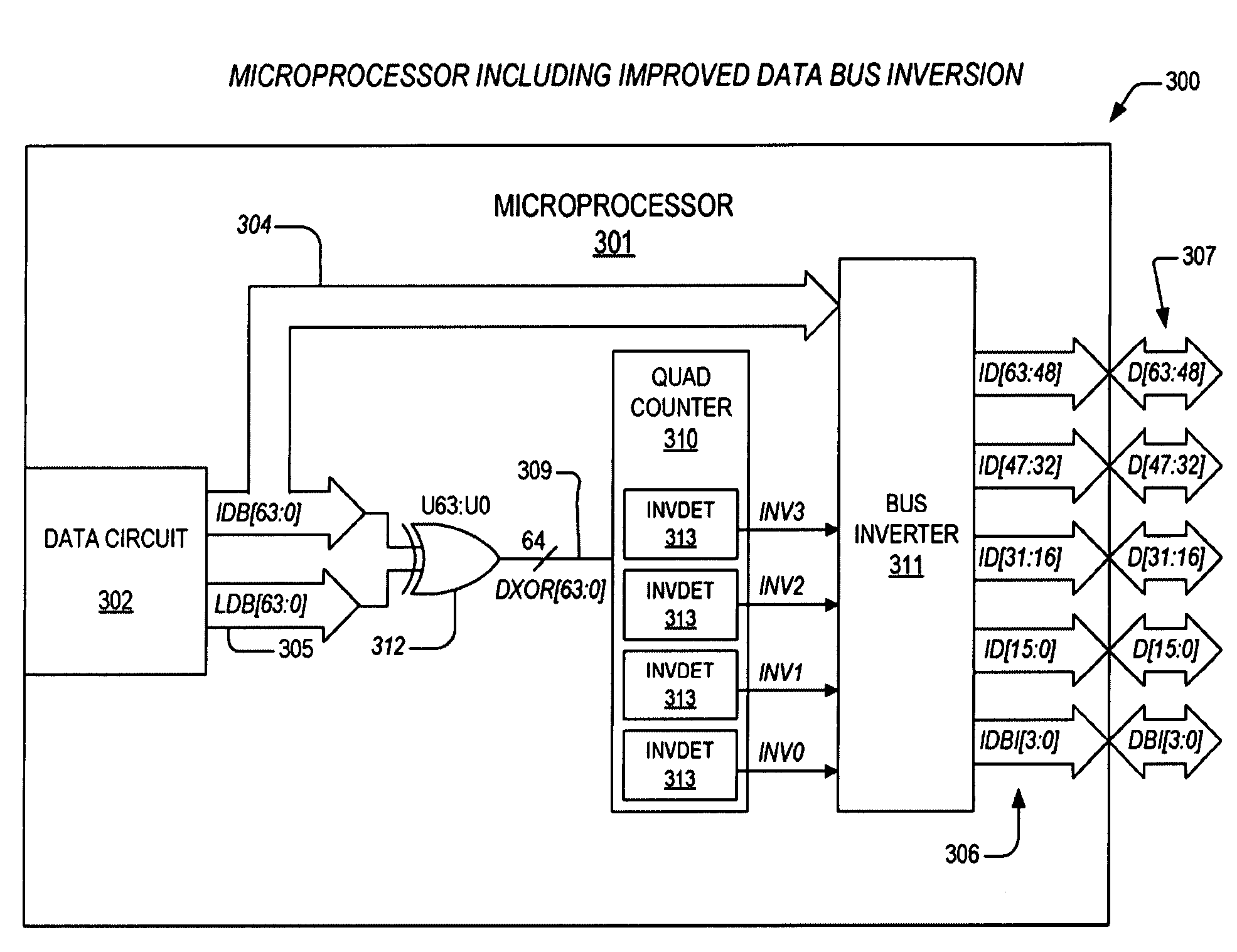
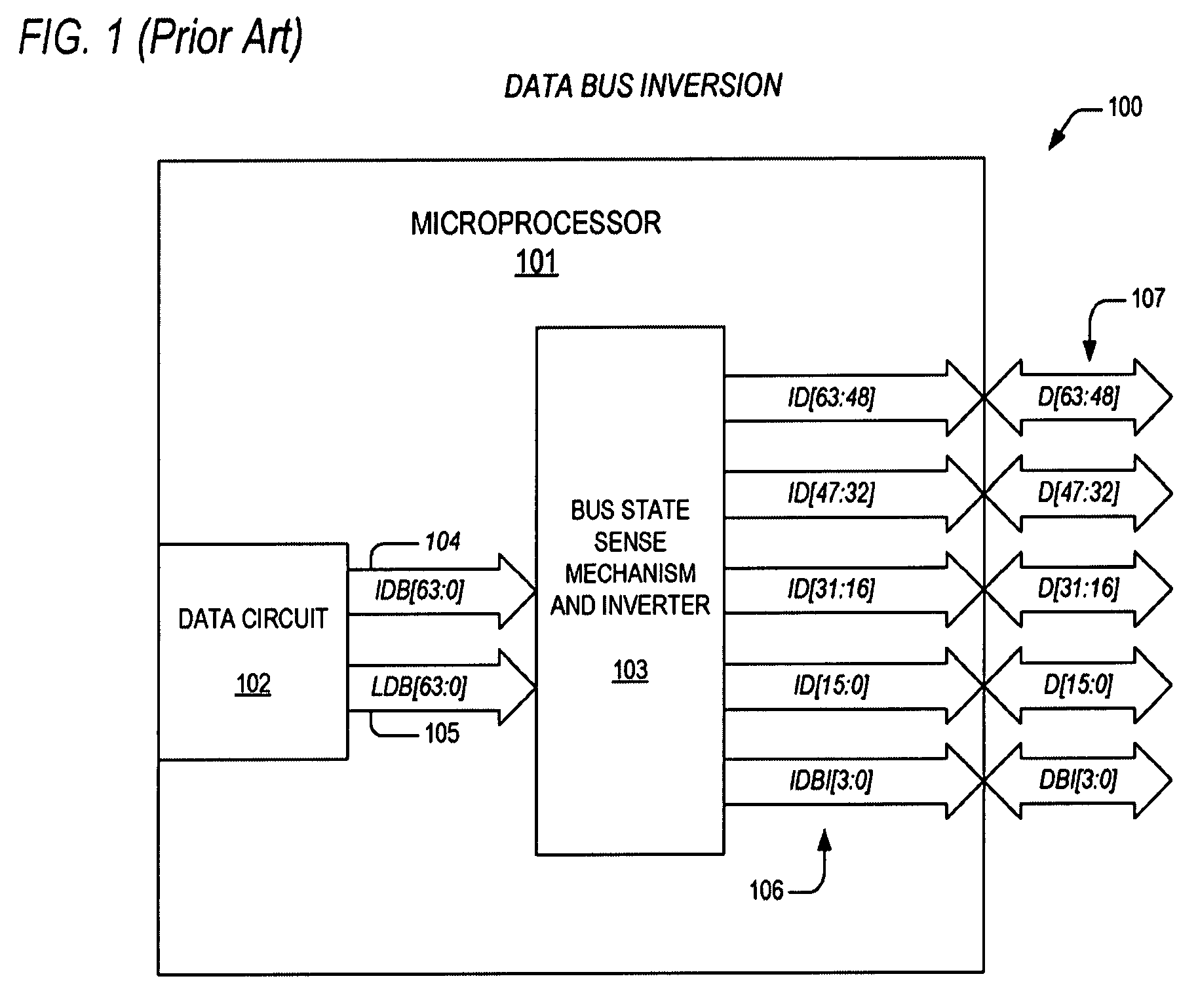
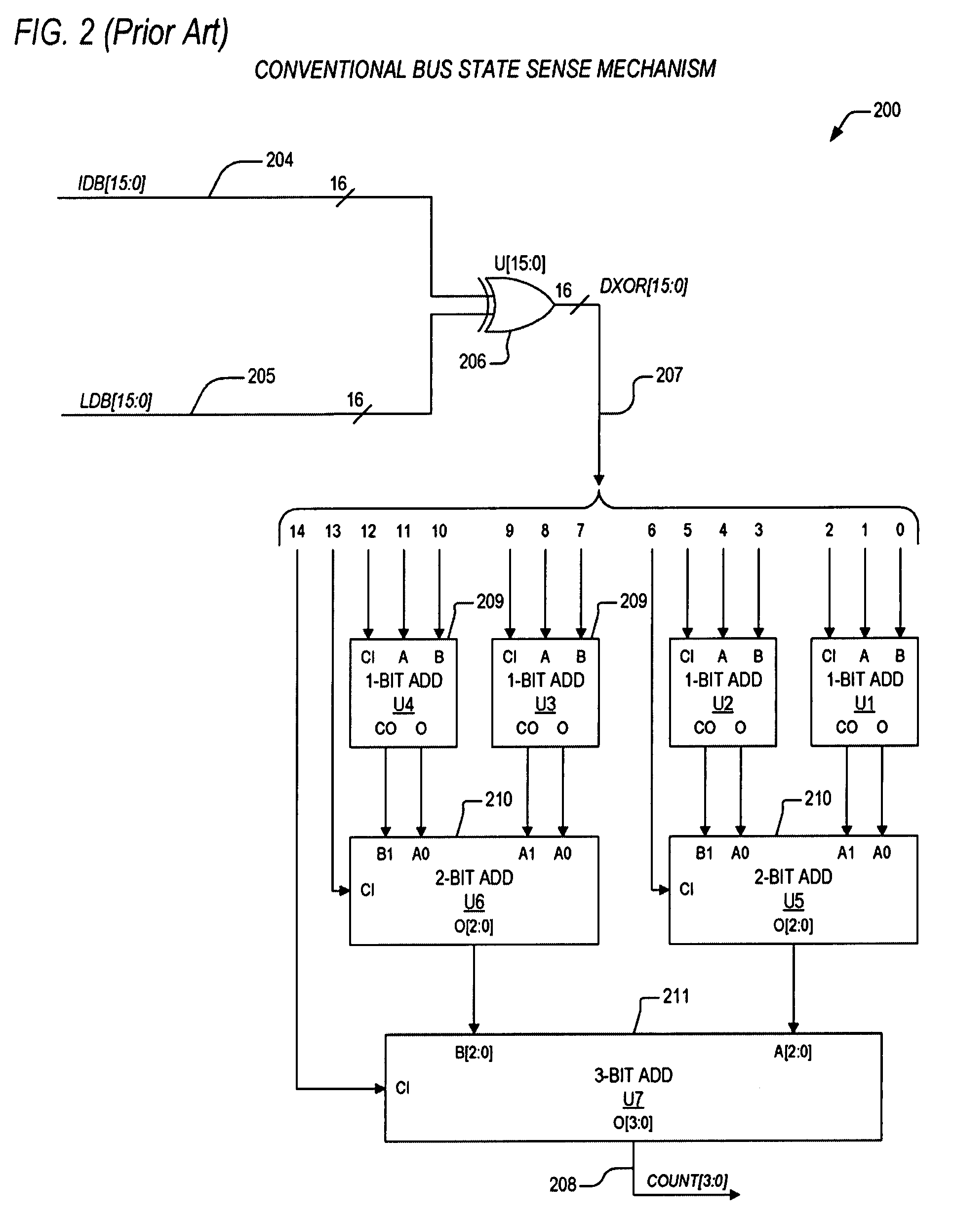
[0028]In view of the above background discussion on bus inversion principles and associated techniques employed within present day microprocessors for detecting the number of bits on a bus which are to be changed during a subsequent bus cycle, a discussion of the limitations of these techniques will now be presented with reference to FIGS. 1-2. Following this discussion, the pr...


PUM


Abstract

A bus inversion apparatus includes exclusive-OR gates and an inversion detector. The exclusive-OR gates are coupled to an instant data bus and a last data bus. The data buses have a corresponding plurality of bits, where the exclusive-OR gates perform a bitwise comparison of the data buses, and provide an exclusive-OR bus. The states of the exclusive-OR bus indicate whether corresponding bits of the data buses are different. The inversion detector counts the number of the corresponding bits that are different, and indicates that the instant data bus should be inverted. The inversion detector has a plurality of left shift circuits, each configured to perform a logical left shift of input bits as directed by the states of shift bits, where outputs of the each of the plurality of left shift circuits indicate a number of a subgroup of the corresponding bits that are different.

Description

BACKGROUND OF THE INVENTION[0001]1. Field of the Invention[0002]This invention relates in general to the field of microelectronics, and more particularly to an apparatus and method for performing data bus inversion within a present day microprocessor.[0003]2. Description of the Related Art[0004]Many present day computer-based systems rely heavily on high-speed parallel buses to transfer address, data, control, and input / output information. The well-known source synchronous quad-pumped data bus that is employed in x86-compatible microprocessors is just one example of a 64-bit data bus that is divided into four data signal subgroups, each consisting of 16 bits. Each of the 16-bit data signal subgroups is routed over a separate path, typically via motherboard traces, and additionally includes source strobe signals and bus inversion signals that are unique to that data signal subgroup. The source strobe signals are strobed by a sending element on the bus to indicate validity of the data...

Claims


Application Information

Patent Timeline
Patent Type & Authority Patents(United States)
IPC IPC(8): G06F13/38G06F13/00
CPCG06F7/02G06F7/607G06F13/4072
Inventor BERTRAM, RAYMOND A.
Owner VIA TECH INC
Why Eureka
Try Eureka