
Method of operating an internal combustion engine

a technology of internal combustion engine and combustion chamber, which is applied in the direction of electrical control, process and machine control, etc., can solve the problems of engine nox production at lower speeds and loads, engine thermal efficiency or engine emissions can be degraded, and the pre-mixed air-fuel temperature may not increase to auto-ignition temperature, so as to improve thermal efficiency and engine emissions, and maintain the stability of hcci combustion

Active Publication Date: 2010-03-02
MAZDA MOTOR CORP
View PDF16 Cites 22 Cited by
  • Summary
  • Abstract
  • Description
  • Claims
  • Application Information

AI Technical Summary

Benefits of technology

The patent describes a method for operating an internal combustion engine using gasoline that combusts by auto-ignition. The method involves adjusting engine operating conditions to bring the temperature of the combustion chamber close to the auto-ignition temperature and producing auto-ignition without needing a spark plug. The method also includes a second mode that involves using a small amount of spark to assist in the ignition process, which can improve thermal efficiency and decrease emissions. The method can be implemented in both low and high engine speed and load conditions to optimize fuel economy and emissions control.

Problems solved by technology

However, as mentioned above, when the engine is operating at lower speeds and lower loads, the pre-mixed air-fuel temperature may not increase to auto-ignition temperature even when the piston reaches the top-dead-center position.
Specifically, at engine operating conditions where combustion chamber temperature is low, thermal efficiency or engine emissions can degrade since auto-ignition may not occur at the appropriate time, even if injecting a part of fuel is implemented in the negative overlap period.
However, the inventors herein have recognized that the amount of NOx produced by the engine at lower speeds and loads can be undesirable if spark assisted HCCI is implemented as described in this patent.

Method used


Image

  • Method of operating an internal combustion engine
  • Method of operating an internal combustion engine
  • Method of operating an internal combustion engine

Examples


second embodiment

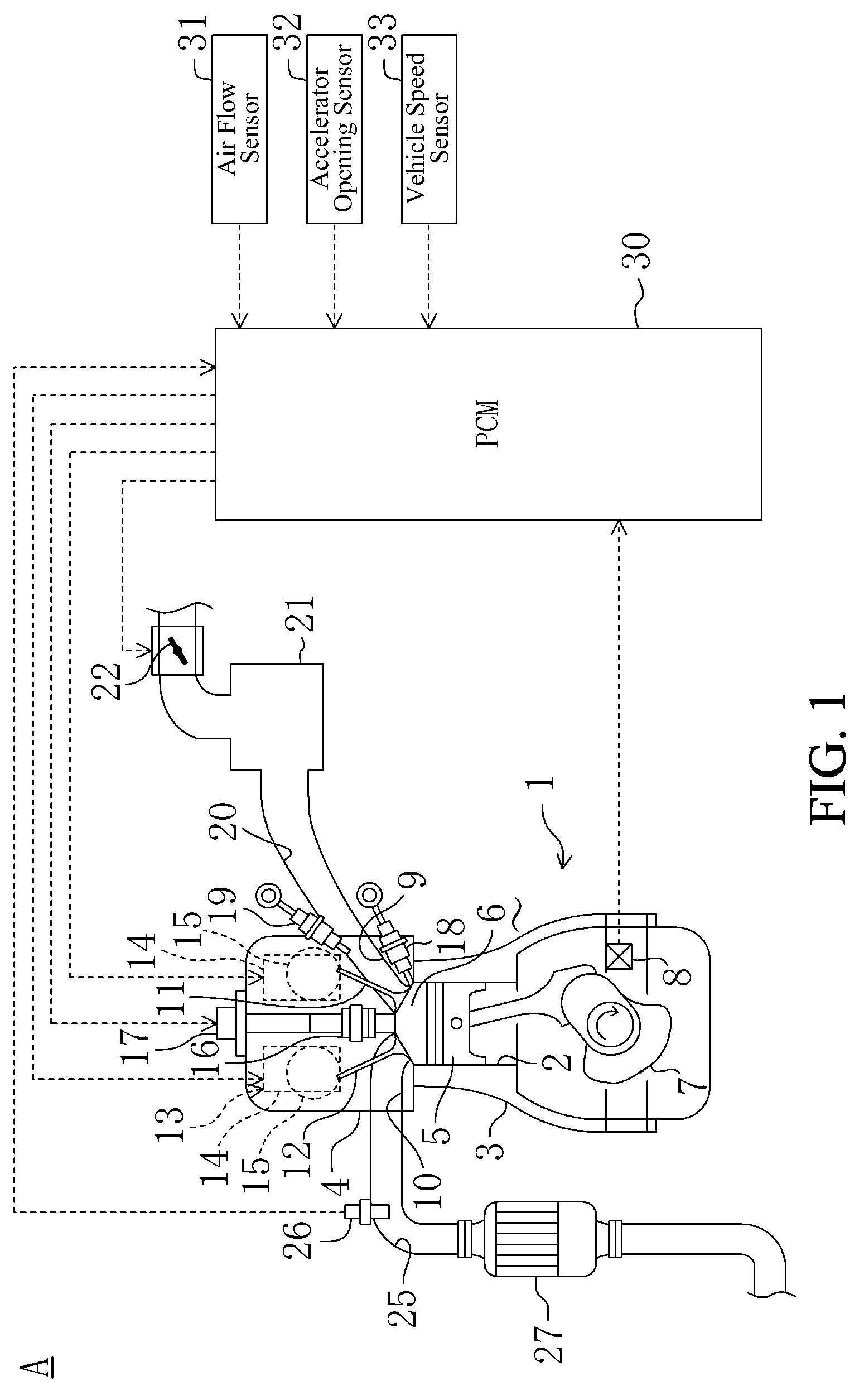
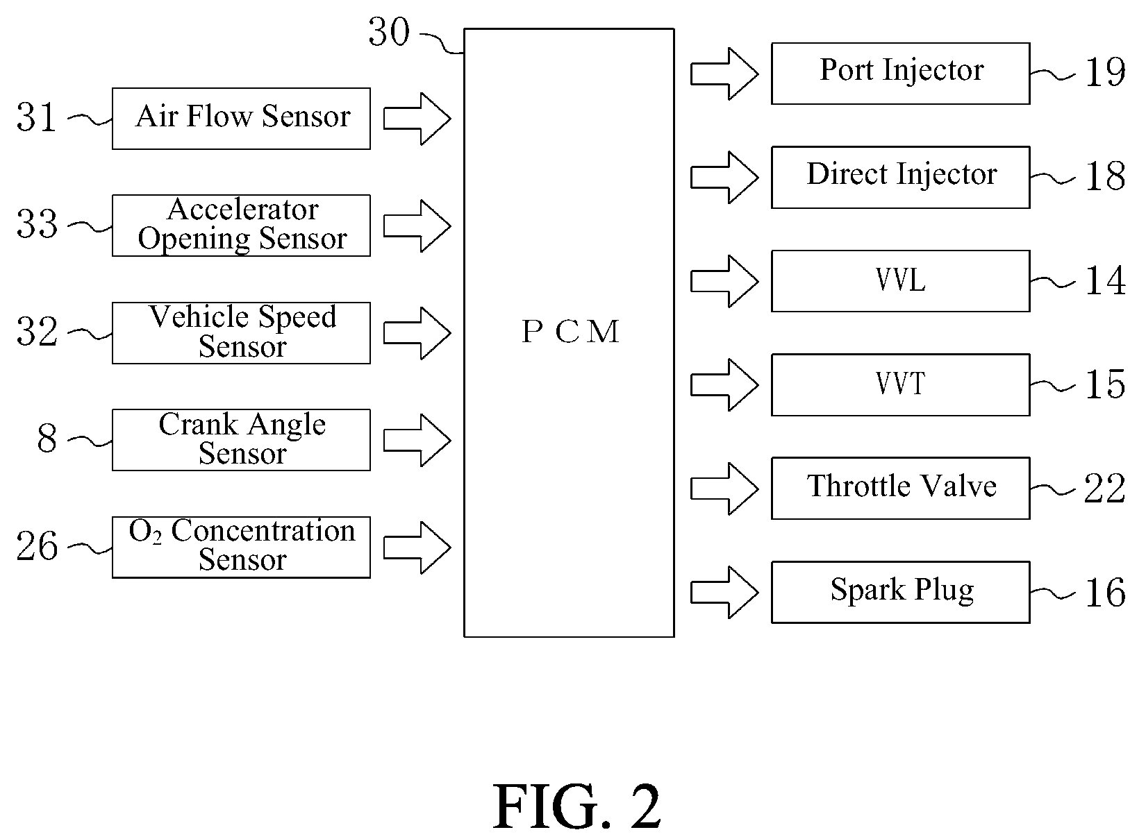
[0080]Next, the second embodiment of the invention will be described in detail based on the drawings. In this embodiment, the entire configuration and the control block diagram of the power train control module 30 (PCM) for performing the control of the engine 1, and the lift curves Lin and Lex of the intake and exhaust valves 11 and 12 by the control of VVL 14 and VVT 15 are similar to that of the first embodiment described above and, thus, the explanation thereof will be omitted herein.

[Outline of Engine Control]

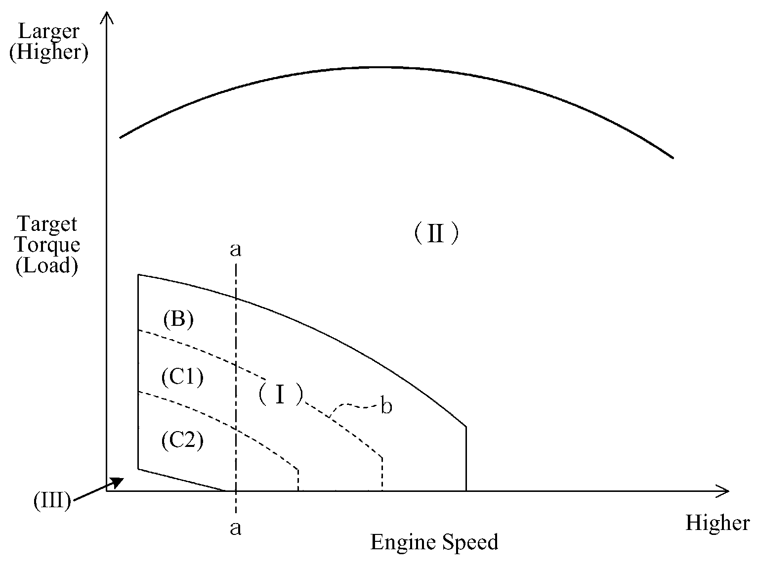
[0081]Specifically, as shown in FIG. 10, an example of the control map is configured so that the substantially homogeneous air-fuel mixture formed inside the cylinder 2 is not directly ignited in the operating range (I) of lower engine load and lower engine speed, but, instead, is compressed by rising of the piston 5, and auto-ignites (i.e., HCCI combustion). In this HCCI combustion, similar to the first embodiment, fuel is injected into the intake port 9 by the port injec...


PUM


Abstract

A method of operating an internal combustion engine having a combustion chamber with a piston and a spark plug, comprising during a first mode, bringing the temperature of the combustion chamber to auto-ignition temperature by adjusting engine operating conditions and producing auto-ignition in said combustion chamber without requiring spark from said spark plug; and during a second mode, bringing the temperature of the combustion chamber close to auto-ignition temperature by adjusting engine operating conditions, forming a small cloud of stratified air-fuel mixture near said spark plug, igniting said fuel cloud by a spark form said spark plug, and then causing cylinder pressure to rise, thereby producing auto-ignition at other sites in said combustion chamber wherein said first mode is implemented in a first operating range and said second mode is implemented only in a second operating range where engine speed and load are lower than said first operating range.

Description

FIELD[0001]The present description relates to a gasoline engine which combusts a compressed premixed air-fuel mixture by auto-ignition. More particularly, the description pertains to a method or system for operating an internal combustion engine having a combustion chamber with a piston and a spark plug which can perform homogeneous charge compression ignition (HCCI) combustion.BACKGROUND AND SUMMARY[0002]In recent years, a new type of gasoline combustion has been demonstrated. In particular, a pre-mixed air-fuel mixture is compressed in a combustion chamber such that the mixture combusts without using a spark plug to initiate the combustion. This type of combustion has been developed to improve fuel economy and emissions of gasoline engines. HCCI combustion may result in higher thermal efficiency as compared to common spark ignition (SI) combustion. This is because HCCI combustion is initiated at a plurality of sites in the combustion chamber. Combustion starts by auto-ignition and...

Claims


Application Information

Patent Timeline
Patent Type & Authority Patents(United States)
IPC IPC(8): F02B17/00F02B3/00
CPCF02B17/00F02D13/0211F02D13/0265F02D41/3041F02M25/0752F02B1/12F02B2075/125F02B2275/16F02D41/006F02D41/3047F02D41/3064F02D2041/001Y02T10/123Y02T10/18F02M26/01Y02T10/12
Inventor YAMASHITA, HIROYUKITANAKA, TATSUYAWATANABE, TOMOMI
Owner MAZDA MOTOR CORP
Learn More