Method of controlling an internal combustion engine and system including the engine

a technology of internal combustion engine and control system, which is applied in the direction of electric control, valve drive, instruments, etc., can solve the problems of increased in-cylinder temperature and pressure, decreased combustion stability, and inability to achieve early ignition, so as to improve the fuel economy and emissions of gasoline engines

Active Publication Date: 2009-04-09
MAZDA MOTOR CORP
View PDF13 Cites 19 Cited by
  • Summary
  • Abstract
  • Description
  • Claims
  • Application Information

AI Technical Summary

Benefits of technology

[0002]In recent years, a new type of gasoline combustion has been demonstrated. In particular, a pre-mixed air-fuel mixture is compressed in a combustion chamber such that the mixture combusts without using a spark plug to initiate the com

Problems solved by technology

However, the inventors herein have recognized that in relatively high load regions, providing a negative overlap period and increasing concentration of oxygen supplied into a combustion chamber according to an internal EGR amount as described above with respect to Japanese Unexamined Patent Application Publication No. 2006-22664, can make it easier to generate an unintended surface ignition within the cylinder, resulting in undesirable early ignition.
However, the inventors herein have recognized that undesirable early ignition can result in a decrease of combustion stability in this related art, e

Method used


Image

  • Method of controlling an internal combustion engine and system including the engine
  • Method of controlling an internal combustion engine and system including the engine
  • Method of controlling an internal combustion engine and system including the engine

Examples


Embodiment Construction

[0047]Hereinafter, an embodiment of the present invention will be described referring to the accompanying drawings.

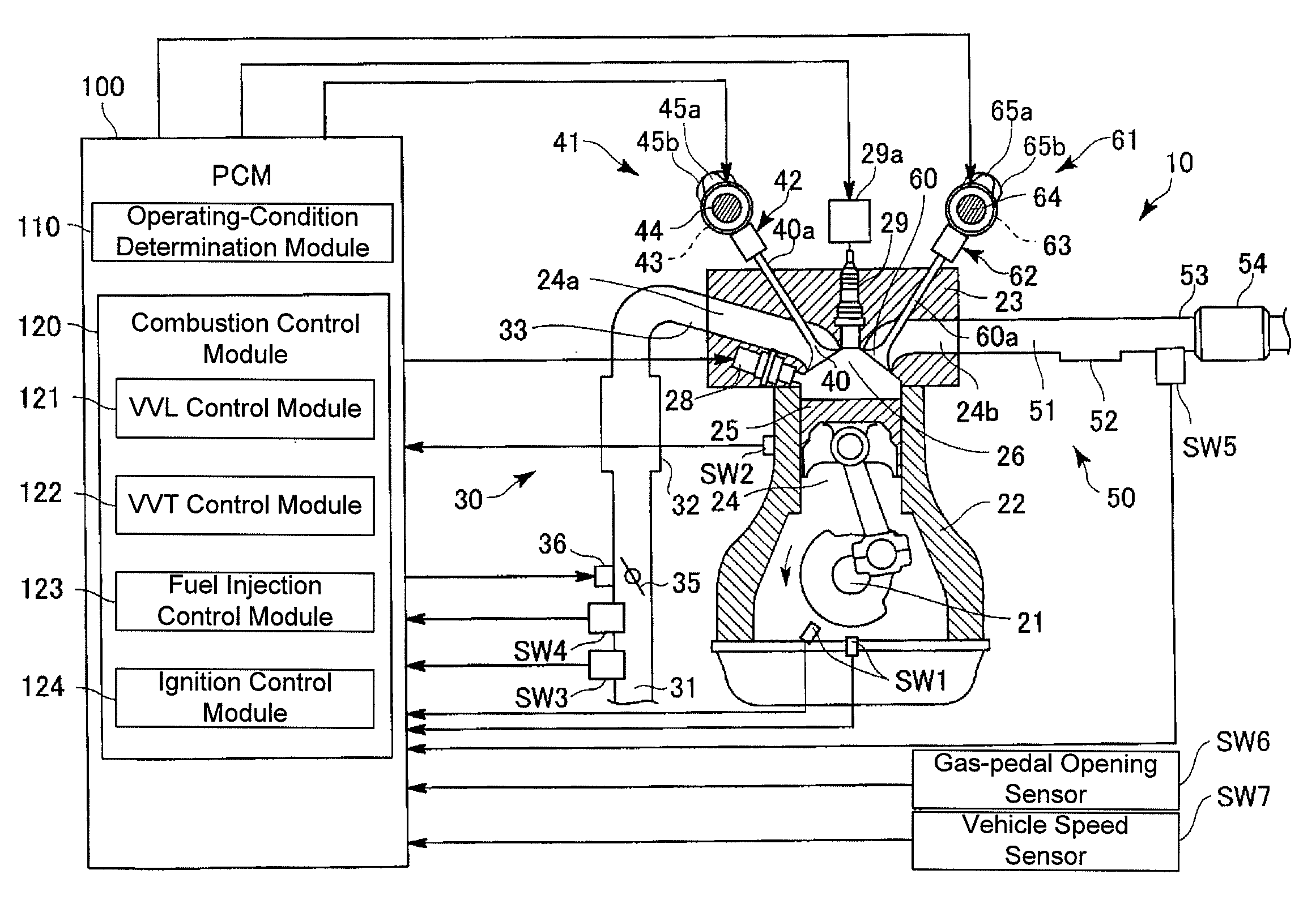
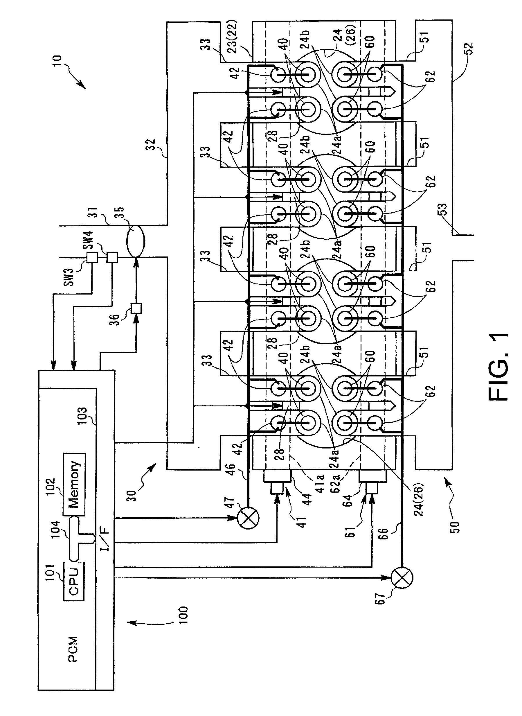
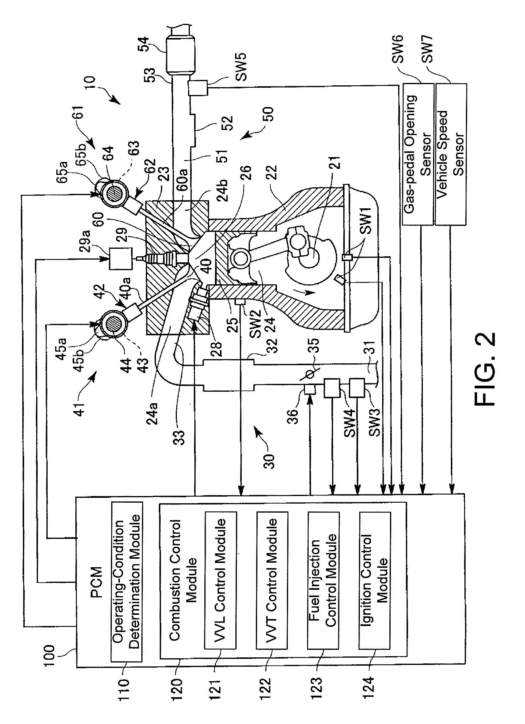
[0048]FIG. 1 is a block diagram showing a schematic configuration of a spark-ignition-type four-cycle gasoline engine 10 according to an embodiment of the present invention. FIG. 2 is a schematic cross-sectional view showing a structure of a cylinder of the engine 10 shown in FIG. 1, and an intake valve 40 and an exhaust valve 60 provided to the engine. FIG. 3 is a schematic view showing a structure of valve operating mechanisms 41 and 61 of the engine 10 shown in FIG. 1.

[0049]In these figures, the engine 10 is mounted on an automobile, and an output shaft of the engine is coupled to driven wheels of the automobile through a power transmission system that includes at least a gear reduction mechanism (not illustrated). The engine 10 includes a cylinder block 22 for rotatably supporting a crankshaft 21, and a cylinder head 23 arranged above the cylinder block 22.

[0050]A p...


PUM


Abstract

A method of controlling an internal combustion engine and system including the engine is provided. The method may include closing an exhaust valve of a combustion chamber of said engine during a cylinder cycle prior to opening an intake valve of said combustion chamber. The method may include, when a desired engine torque is a predetermined torque or greater, supplying a first pilot fuel into said combustion chamber after said exhaust valve closing and supplying a first main fuel into said combustion chamber after the combustion of said first preliminary fuel during the cylinder cycle. The method may include, when a desired engine torque is less than said predetermined torque, supplying a second pilot fuel into said combustion chamber after said exhaust valve closing during the cylinder cycle and supplying a second main fuel into said combustion chamber after the supplying of said second pilot fuel into said combustion chamber.

Description

TECHNICAL FIELD[0001]The present description relates to a gasoline engine which combusts a compressed premixed air-fuel mixture by auto-ignition. More particularly, the description pertains to a method for operating an internal combustion engine or system which can perform homogeneous charge compression ignition (HCCI) combustion.BACKGROUND AND SUMMARY[0002]In recent years, a new type of gasoline combustion has been demonstrated. In particular, a pre-mixed air-fuel mixture is compressed in a combustion chamber such that the mixture combusts without using a spark plug to initiate the combustion. This type of combustion, referred as homogeneous charge compression ignition (HCCI) combustion, has been developed to improve fuel economy and emissions of gasoline engines. HCCI may also be referred to as compressed self ignition.[0003]To perform this HCCI operation, a technology is known for keeping combusted gas in a combustion chamber of the engine as an internal exhaust gas recirculation...

Claims


Application Information

Patent Timeline
IPC IPC(8): F02D41/30F02M43/00F01L1/34
CPCF01L1/08Y02T10/47F01L1/34F01L13/0005F01L13/0031F01L2001/0537F01L2800/00F01L2820/042F02D41/006F02D41/3041F02D41/402F02D41/403F02D2041/001F02M43/00F02M45/00Y02T10/44F01L1/14Y02T10/40
Inventor YAMASHITA, HIROYUKIYAMAUCHI, TAKEOSETO, MASATOSHI
Owner MAZDA MOTOR CORP
Why Eureka
Try Eureka