
Wind turbine blade transportation system and method

a technology transportation systems, applied in the direction of transportation and packaging, transportation items, machines/engines, etc., can solve the problems of increasing transportation costs, affecting the transportation of wind turbine blades, and affecting the transportation of long turbine blades

Active Publication Date: 2010-03-02
TRANSPORTATION TECH SERVICES
View PDF12 Cites 62 Cited by
  • Summary
  • Abstract
  • Description
  • Claims
  • Application Information

AI Technical Summary

Benefits of technology

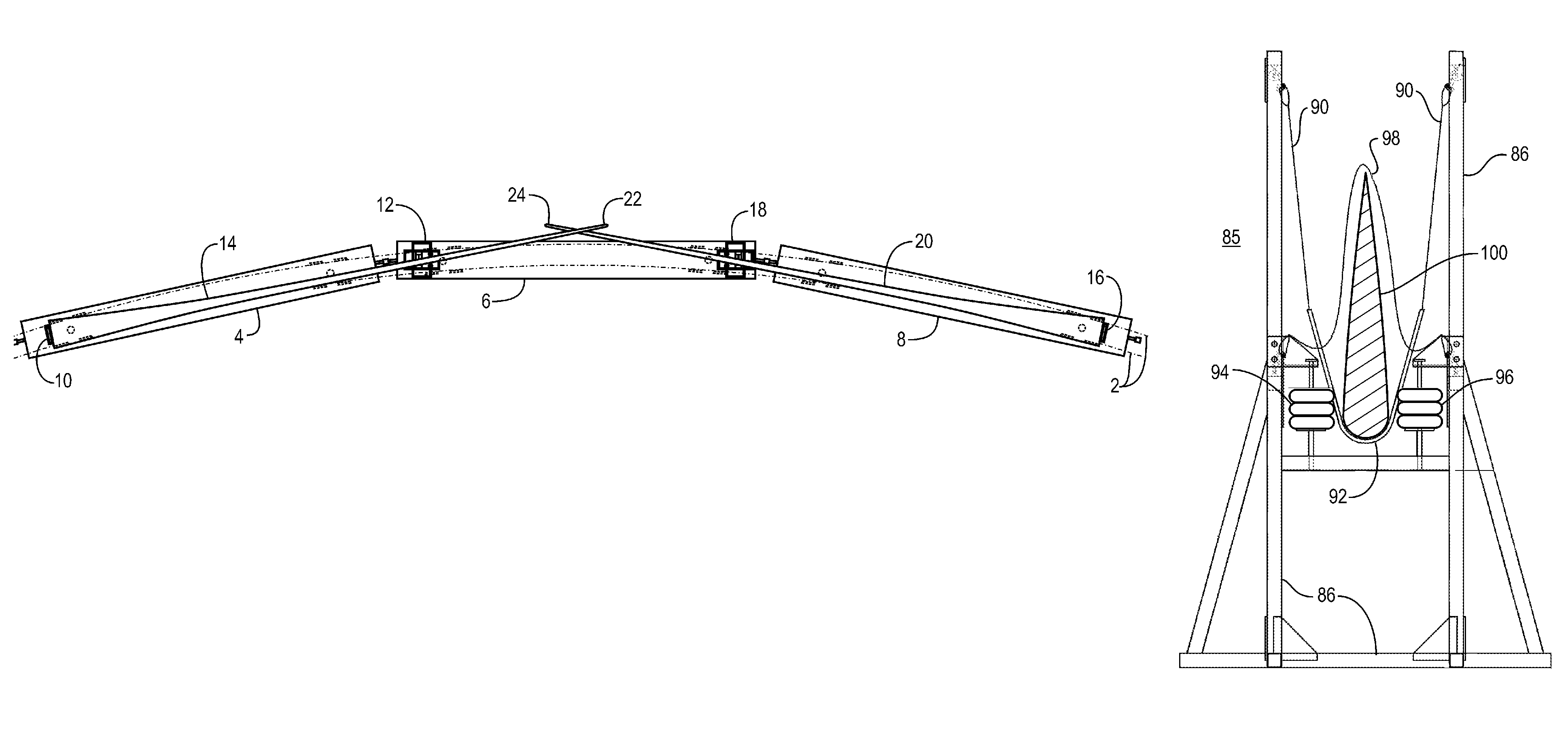
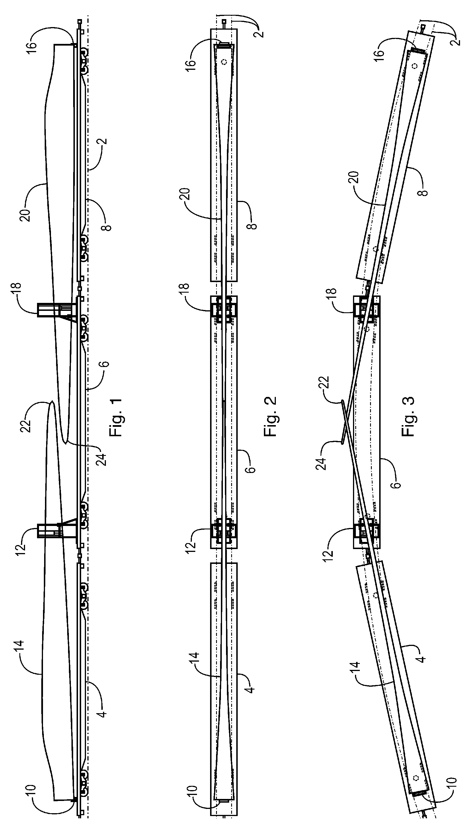
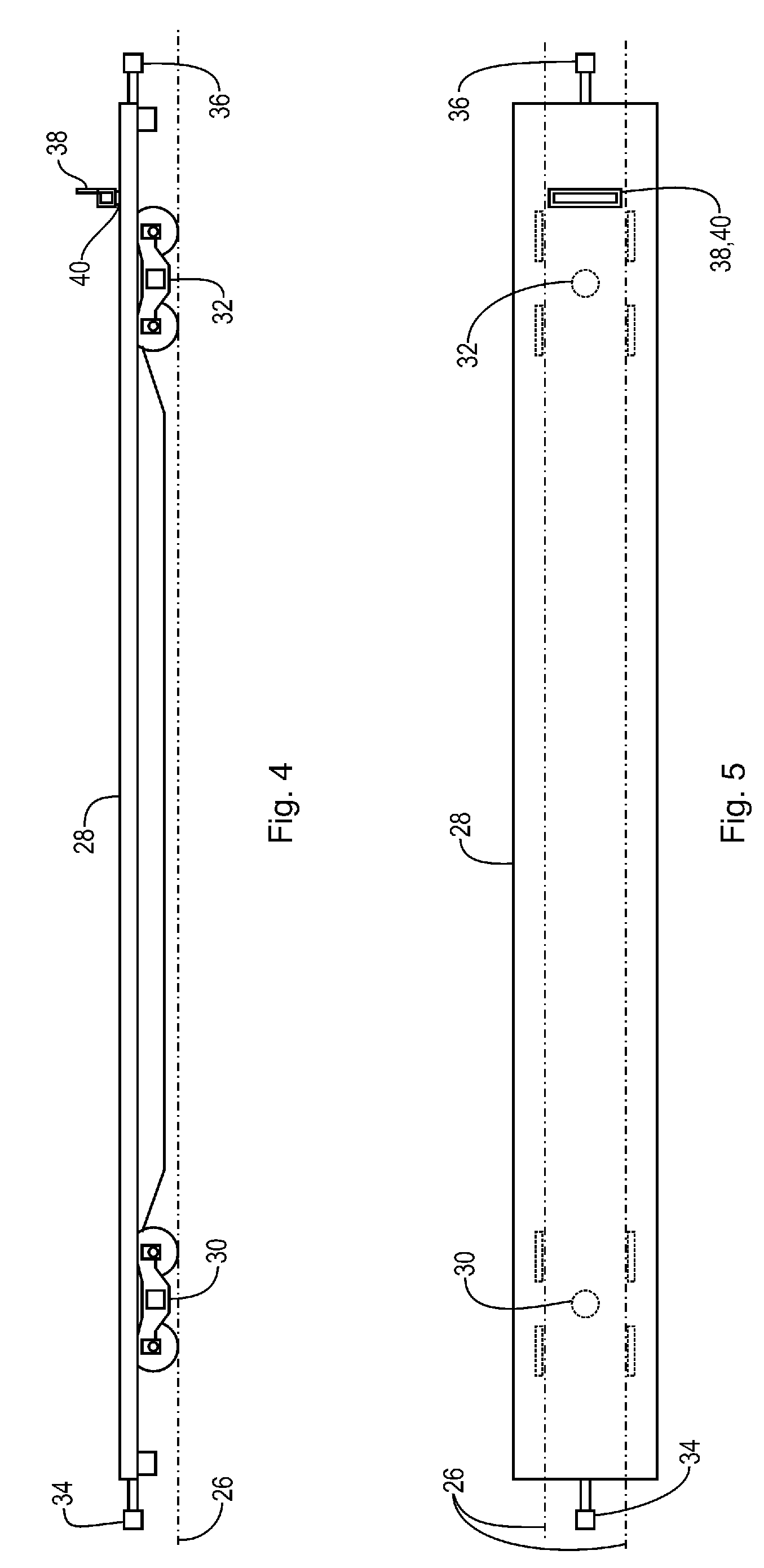
"The present invention provides a system and method for transporting an airfoil over a railroad using a first and second railcar. The system includes a bracket fixed to the root end of the airfoil and connected to the first railcar, a sling stand connected to the second railcar, and a sling hung from the sling stand to support the midsection of the airfoil and accommodate misalignment during transport. The method includes connecting the bracket to the first railcar, aligning the tip end of the airfoil with the second railcar, and supporting the midsection of the airfoil with the sling. The system and method allow for longitudinal movement of the airfoil while limiting lateral movement and accommodating misalignment during transport."

Problems solved by technology

The various components are expensive to manufacture, and include delicate components that must be protected and handled properly during transportation.
The transportation issues are exacerbated in that the components may be transported using plural modes during their journey.
Transportation of long turbine blades presents significant challenges to transportation engineers, particularly in the case of railroads, where the railroad profile is tightly limited and the trains must traverse curved sections and complex rail yards.

Method used


Image

  • Wind turbine blade transportation system and method
  • Wind turbine blade transportation system and method
  • Wind turbine blade transportation system and method

Examples


Embodiment Construction

[0035]Illustrative embodiments and exemplary applications will now be described with reference to the accompanying drawings to disclose the advantageous teachings of the present invention.

[0036]While the present invention is described herein with reference to illustrative embodiments for particular applications, it should be understood that the invention is not limited thereto. Those having ordinary skill in the art and access to the teachings provided herein will recognize additional modifications, applications, and embodiments within the scope hereof and additional fields in which the present invention would be of significant utility.

[0037]In considering the detailed embodiments of the present invention, it will be observed that the present invention resides primarily in combinations of steps to accomplish various methods or components to form various apparatus and systems. Accordingly, the apparatus and system components and method steps have been represented where appropriate by...


PUM


Abstract

A system for transporting an airfoil having a root end, a tip end, and a midsection over a railroad, utilizing a first railcar coupled to a second rail car. The system includes a bracket fixed to the root end of the airfoil and also connected to the first railcar, where the bracket is oriented to align the tip end of the airfoil toward the second rail car. A sling stand is connected to the second railcar, and a sling is hung from the sling stand and aligned to engage and support the midsection of the airfoil, and thereby accommodates misalignment during transport over the railroad. A pair of rollers are disposed on either side of the airfoil to limit lateral movement thereof.

Description

BACKGROUND OF THE INVENTION[0001]1. Field of the Invention[0002]The present invention relates to transporting wind turbine blades. More specifically, the present invention relates to a system and method for transporting long airfoils via railroad using plural railcars.[0003]2. Description of the Related Art[0004]Large-scale wind turbines are used to generate electrical power. Such wind turbines consist of a tall tower with a generator nacelle rotatably coupled about the top of tower's vertical axis. A rotor hub extends out a horizontal axis of the nacelle. Two or more turbine blades are connected to the rotor hub at right angles to the horizontal axis. During operation, prevailing winds cause the turbine blades to rotate about the rotor hub's horizontal axis. The rotational forces are coupled to a generator within the nacelle, which produces electricity. The nacelle rotates about the vertical axis of the tower to maintain the wind turbine blades in proper orientation with the direct...

Claims


Application Information

Patent Timeline
Patent Type & Authority Patents(United States)
IPC IPC(8): B60P3/022B60P3/00B60P3/40
CPCB60P3/40B61D3/16F03D1/005Y02E10/72F03D13/40
Inventor LANDRUM, SCOTT C.KING, T. CHRISTOPHER
Owner TRANSPORTATION TECH SERVICES
Learn More