Method for producing doped regions in a substrate, and photovoltaic cell

a substrate and doping technology, applied in the field of photovoltaic or solar cells, can solve the problems of difficult industrial implementation, cost and the number of steps needed to produce doping structures, and high cost and complexity

Inactive Publication Date: 2010-03-02
COMMISSARIAT A LENERGIE ATOMIQUE ET AUX ENERGIES ALTERNATIVES
View PDF9 Cites 9 Cited by
  • Summary
  • Abstract
  • Description
  • Claims
  • Application Information

AI Technical Summary

Benefits of technology

[0022]Thus, a method of this embodiment makes it possible to produce doping structures on the rear face of the substrate while protecting the rest of the substrate from the exodiffusion of the doping agents by the oxide deposit provided before the annealing step. The use of doping pastes makes it possible to reduce the costs of industrial implementation with respect to the plasma depositions performed in the methods of the aforementioned prior art.
[0024]Thus, a method according to the embodiment allows for a simultaneous production of doping structures on the rear face of the substrate while ensuring electrical isolation between the doping structures formed by the insertion of the oxide before the annealing step. This method therefore makes it possible to reduce the number of steps for producing doped regions in a substrate, in particular in the production of RCC cells.
[0040]Thus, it is possible to produce photovoltaic cells from a substrate of which the doped regions have been produced according to this method. This method for producing a photovoltaic cell comprises a reduced number of steps owing to the reduced number of steps in the production of doped regions in a substrate. The costs are also reduced owing to the use of doping pastes with respect to the plasma deposits produced in the methods of the prior art. In addition, the photovoltaic cells obtained by this method have a conversion efficiency superior to that of standard photovoltaic cells, i.e. non-RCC cells.

Problems solved by technology

The disadvantages of such a method are the cost and the number of steps needed to produce doping structures.
Again, the disadvantages of such a method are the cost and an industrial implementation which is difficult to carry out.

Method used


Image

  • Method for producing doped regions in a substrate, and photovoltaic cell
  • Method for producing doped regions in a substrate, and photovoltaic cell
  • Method for producing doped regions in a substrate, and photovoltaic cell

Examples


Embodiment Construction

[0016]Thus there is a need for proposing a method for producing doped regions, or doping structures, in a substrate, that comprises fewer steps than the methods of the prior art, and that is economically beneficial for industrial implementation.

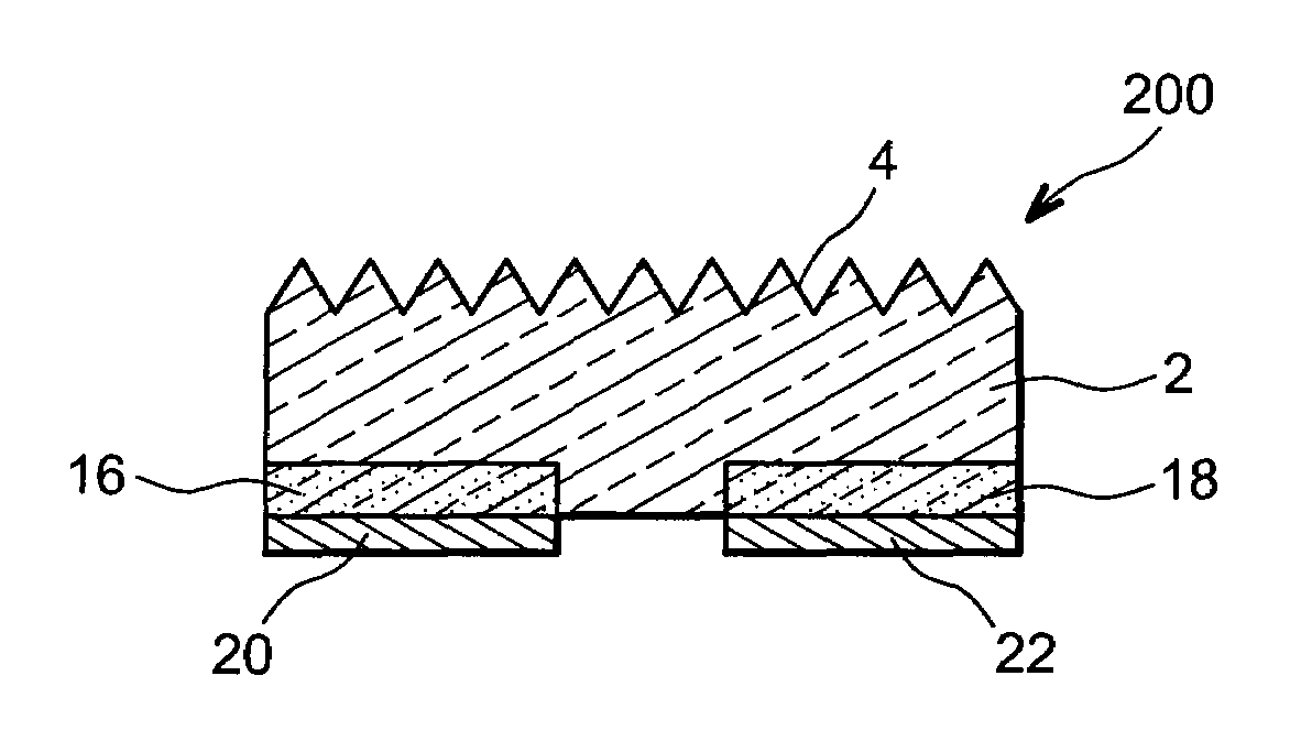
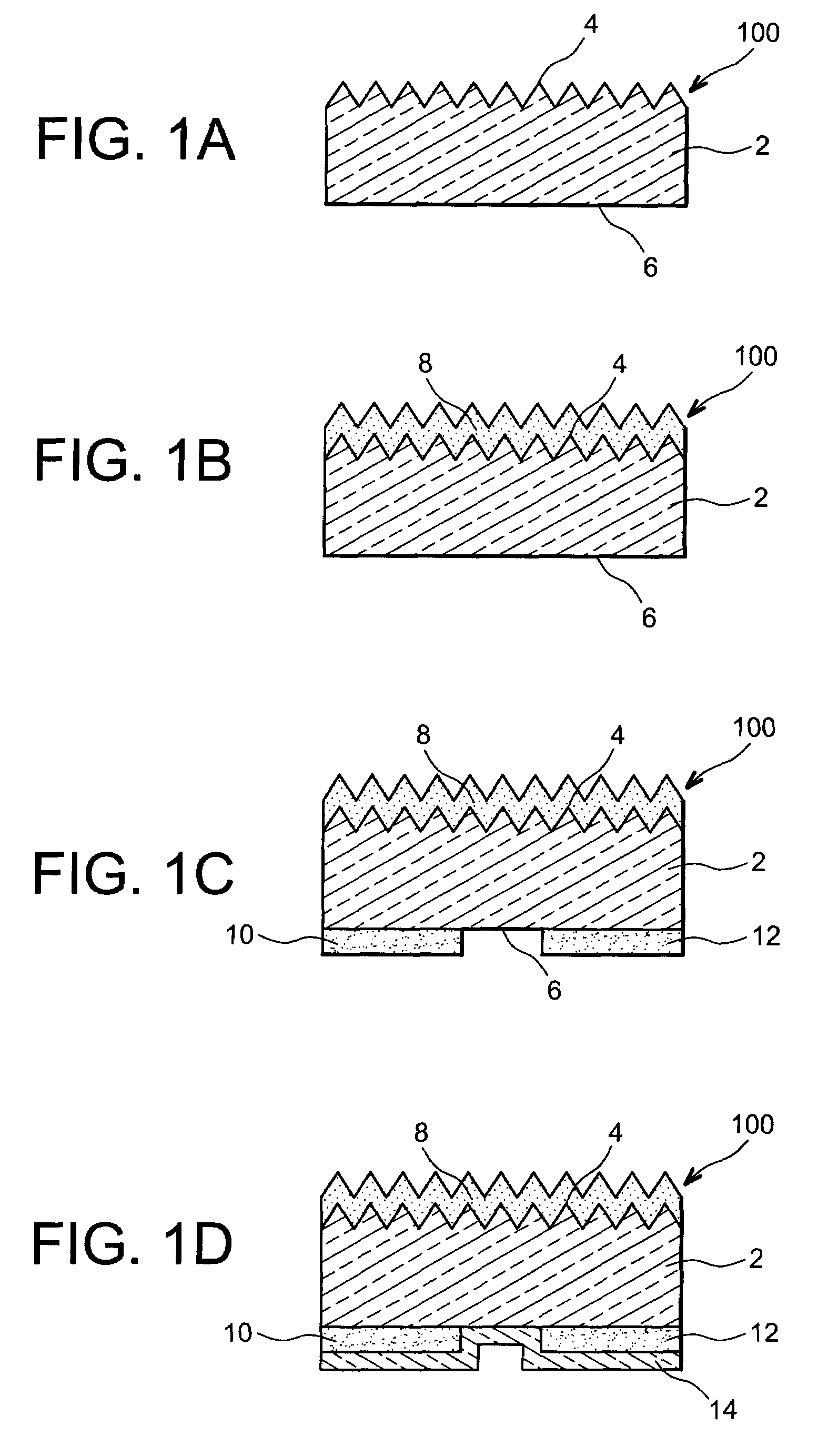
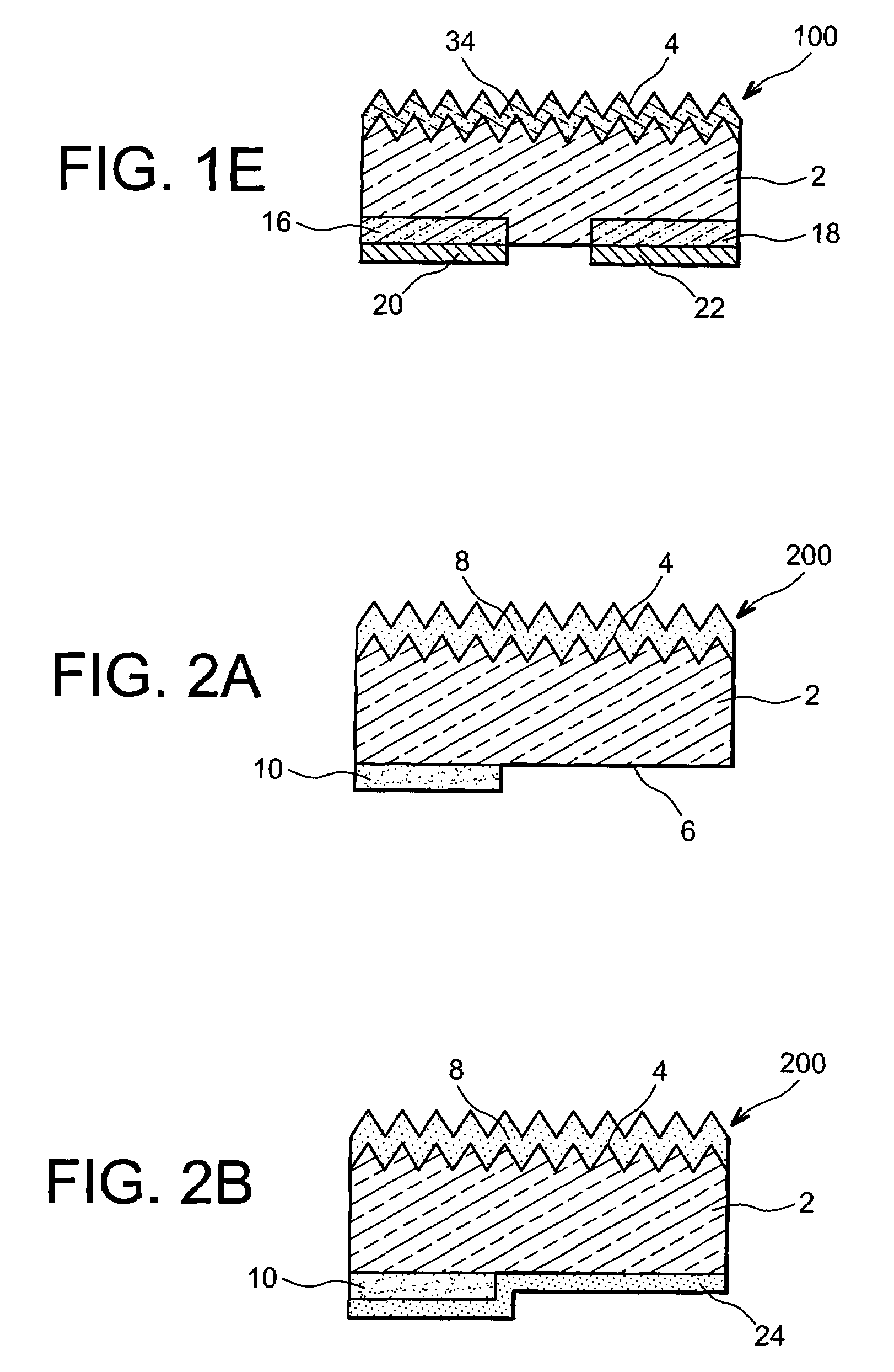
[0017]To do this, an embodiment proposes a method for producing doped regions on the rear face of a photovoltaic cell, including at least the steps of:

[0018]a) depositing a first doping paste comprising doping agents with a first type of conductivity on a face, called the rear face, of a semiconductor-based substrate according to a pattern consistent with the desired distribution of regions doped with the first type of conductivity in the substrate,

[0019]b) depositing an oxide layer at least on the portions of the rear face of the substrate not covered with the doping paste,

[0020]c) annealing the substrate at a temperature diffusing the doping agents in the substrate and forming doped regions, in the substrate, under the doping paste.

[0021]By...


PUM


Abstract

Method for producing doped regions on the rear face of a photovoltaic cell. A doping paste with a first type of conductivity is deposited on a rear face of a semiconductor-based substrate according to a pattern consistent with the desired distribution of regions doped with the first type of conductivity. Then, an oxide layer is deposited at least on the portions of the rear face of the substrate not covered with the doping paste. Finally, an annealing of the substrate diffuses the doping agents in the substrate and forms doped regions under the doping paste.

Description

TECHNICAL FIELD AND PRIOR ART[0001]This invention relates to the field of photovoltaic or solar cells, and more specifically the field of photovoltaic cells with rear contacts, i.e. comprising metal contacts and a PN junction on a face opposite the face intended to receive light radiation.[0002]The photovoltaic cells can comprise metal contacts on the front face (for example in the form of a grid) and on the rear face. There are also photovoltaic cells, called RCC cells (Rear Contact Cell), or IBC (Interdigitated Back Contact) cells, comprising the PN junction and the metal contacts only on the rear face. Regardless of the structure of the metal contacts (front and rear faces or only rear face), a photovoltaic cell reflects a portion of the light radiation entering the cell through the front face: these are the losses due to reflectivity. By comparison with cells comprising metal contacts on the front face and on the rear face, RCC cells have lower reflectivity losses due to the abs...

Claims


Application Information

Patent Timeline
Patent Type & Authority Patents(United States)
IPC IPC(8): H01L21/38
CPCH01L31/0288H01L31/1804H01L31/0682Y02E10/547Y02P70/50
Inventor VESCHETTI, YANNICKBETTINELLI, ARMAND
Owner COMMISSARIAT A LENERGIE ATOMIQUE ET AUX ENERGIES ALTERNATIVES
Why Eureka
Try Eureka