Voltage boost circuit and voltage boosting method using voltage boost clock signal with varying frequency

a voltage boost circuit and clock signal technology, applied in the direction of electric variable regulation, process and machine control, instruments, etc., can solve the problem of excessive operation current of the voltage boost circui

Inactive Publication Date: 2010-03-02
SAMSUNG ELECTRONICS CO LTD
View PDF16 Cites 40 Cited by
  • Summary
  • Abstract
  • Description
  • Claims
  • Application Information

AI Technical Summary

Problems solved by technology

Therefore, under a condition other than the condition where the load current is at a maximum, the operational current of the voltage boost circuit may flow excessively.

Method used


Image

  • Voltage boost circuit and voltage boosting method using voltage boost clock signal with varying frequency
  • Voltage boost circuit and voltage boosting method using voltage boost clock signal with varying frequency
  • Voltage boost circuit and voltage boosting method using voltage boost clock signal with varying frequency

Examples


Embodiment Construction

[0025]Hereinafter, exemplary embodiments of the present invention will be described more fully with reference to the accompanying drawings, in which exemplary embodiments of the invention are shown.

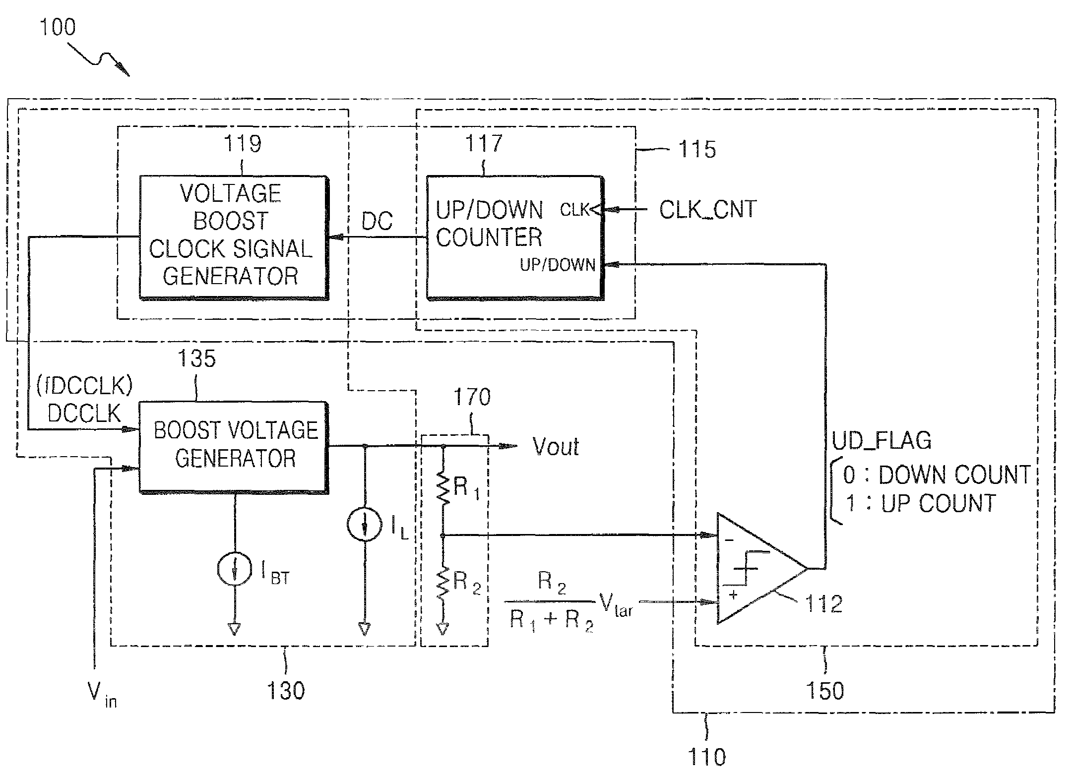
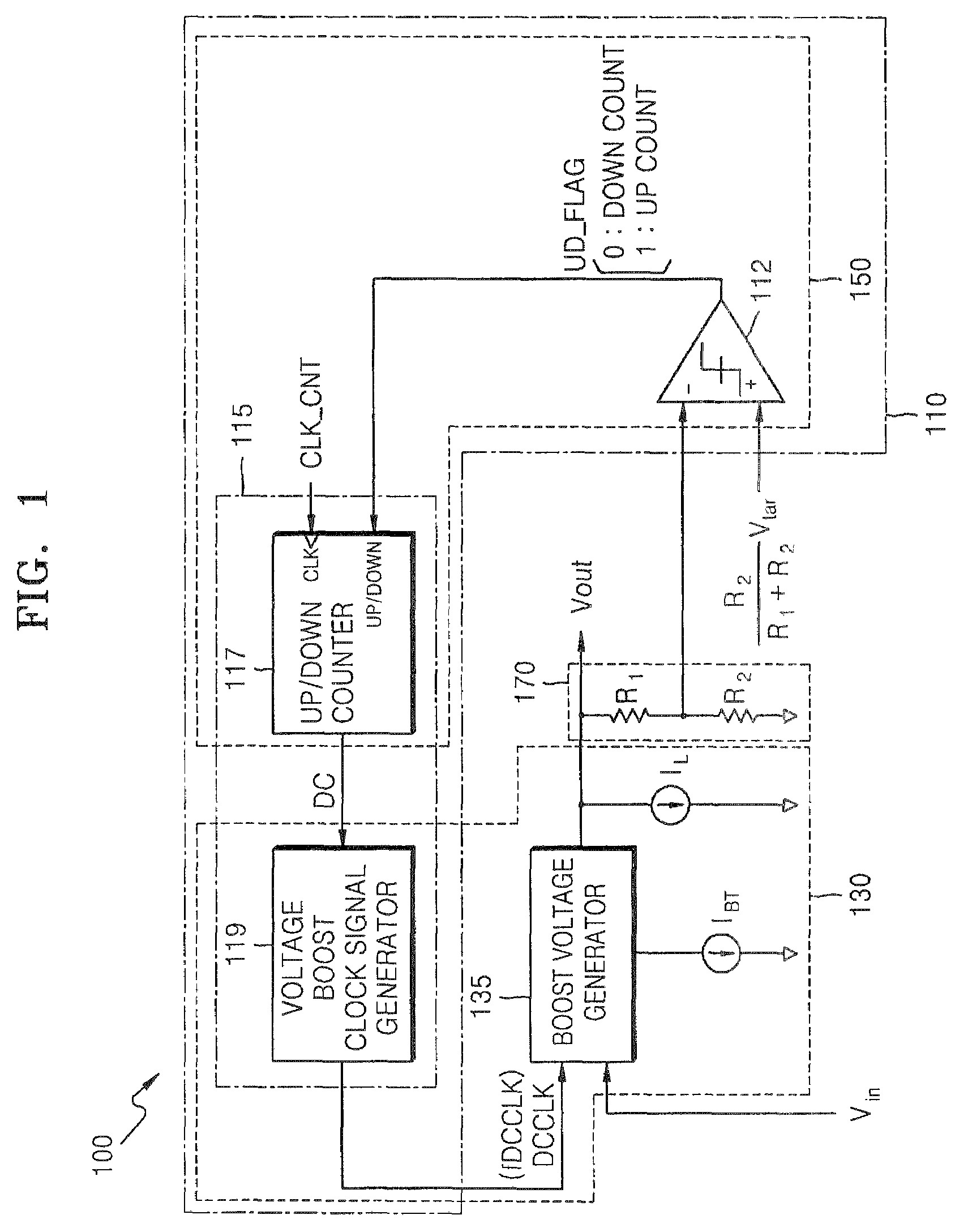
[0026]FIG. 1 is a block diagram of a voltage boost circuit 100 that boosts voltage using a voltage boost clock signal with varying frequency, according to an exemplary embodiment of the present invention.

[0027]Referring to FIG. 1, the voltage boost circuit 100 includes a boost voltage generator 135 and a boost voltage frequency control unit 110. The boost voltage generator 135 responds to a voltage boost clock signal DCCLK in order to boost the input voltage VIN and outputs the boosted input voltage as an output boost voltage VOUT. The boost voltage frequency control unit 110 responds to the result UP / DOWN obtained by comparing the level of the output boost voltage VOUT and the level of a target boost voltage VTAR in order to change a boost voltage frequency fDCCLK of the voltage boost cl...


PUM


Abstract

A voltage boost circuit and a method of boosting voltage using a voltage boost clock signal with varying frequency, in which the voltage boost circuit includes a boost voltage generator that responds to a voltage boost clock signal in order to boost an input voltage and outputs the boosted input voltage as an output boost voltage; and a boost voltage frequency control unit that responds to the result obtained by comparing a level of the output boost voltage and a level of a target boost voltage so as to change the boost voltage frequency of the voltage boost clock signal and outputs the voltage boost clock signal having the changed boost voltage frequency. The voltage boost circuit and the voltage boosting method can prevent a waste of the operating current during the boosting of the voltage.

Description

CROSS-REFERENCE TO RELATED PATENT APPLICATION[0001]This application claims the benefit of Korean Patent Application No. 10-2006-0031928, filed on Apr. 7, 2006, in the Korean Intellectual Property Office, the disclosure of which is incorporated herein in its entirety by reference.BACKGROUND OF THE INVENTION[0002]1. Technical Field[0003]The present disclosure relates to a voltage boost circuit and a method of boosting voltage and, more particularly, to a voltage boost circuit and a method of boosting voltage using a voltage boost clock signal with varying frequency.[0004]2. Discussion of Related Art[0005]A voltage boosting circuit is a circuit that increases a voltage level of a received input voltage and outputs the increased voltage.[0006]The level of boost voltage output by a general voltage boost circuit is proportional to a boost voltage frequency of a voltage boost clock signal and the amount of operational current of the voltage boost clock signal. In addition, the amount of lo...

Claims


Application Information

Patent Timeline
Patent Type & Authority Patents(United States)
IPC IPC(8): G05F1/00
CPCH02M3/156G11C5/14G11C7/20
Inventor CHUNG, KYU-YOUNG
Owner SAMSUNG ELECTRONICS CO LTD
Why Eureka
Try Eureka