
Dual mode weather and air surveillance radar system

Inactive Publication Date: 2010-03-02
BARON SERVICES
View PDF40 Cites 25 Cited by
  • Summary
  • Abstract
  • Description
  • Claims
  • Application Information

AI Technical Summary

Benefits of technology

[0012]An objective of the present invention is to provide a radar system that can operate in two modes, but occupy a minimum space, and maximize the use of common components, thus reducing costs required for parts and maintenance.

Problems solved by technology

This requires sufficient space to install and operate such hardware.
It also results in increased costs for the hardware and its maintenance.
These radars however are only examples of achieving multi-mode capability in the confines of a small air platform.
Heretofore, there is not a successfully deployed multi-mode radar for use at air fields, for example, that need a weather radar in addition to air surveillance capability.

Method used


Image

  • Dual mode weather and air surveillance radar system
  • Dual mode weather and air surveillance radar system
  • Dual mode weather and air surveillance radar system

Examples


Embodiment Construction

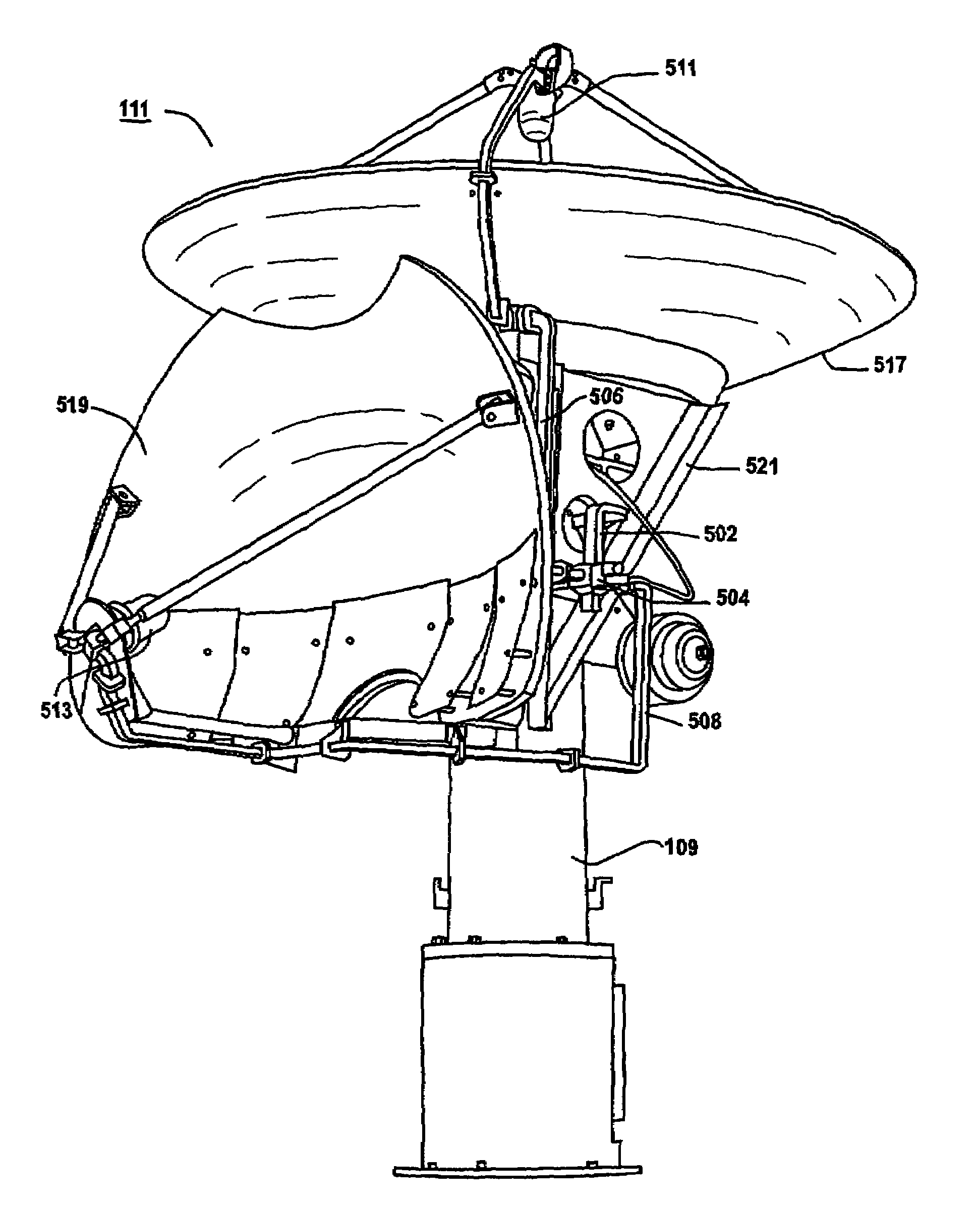
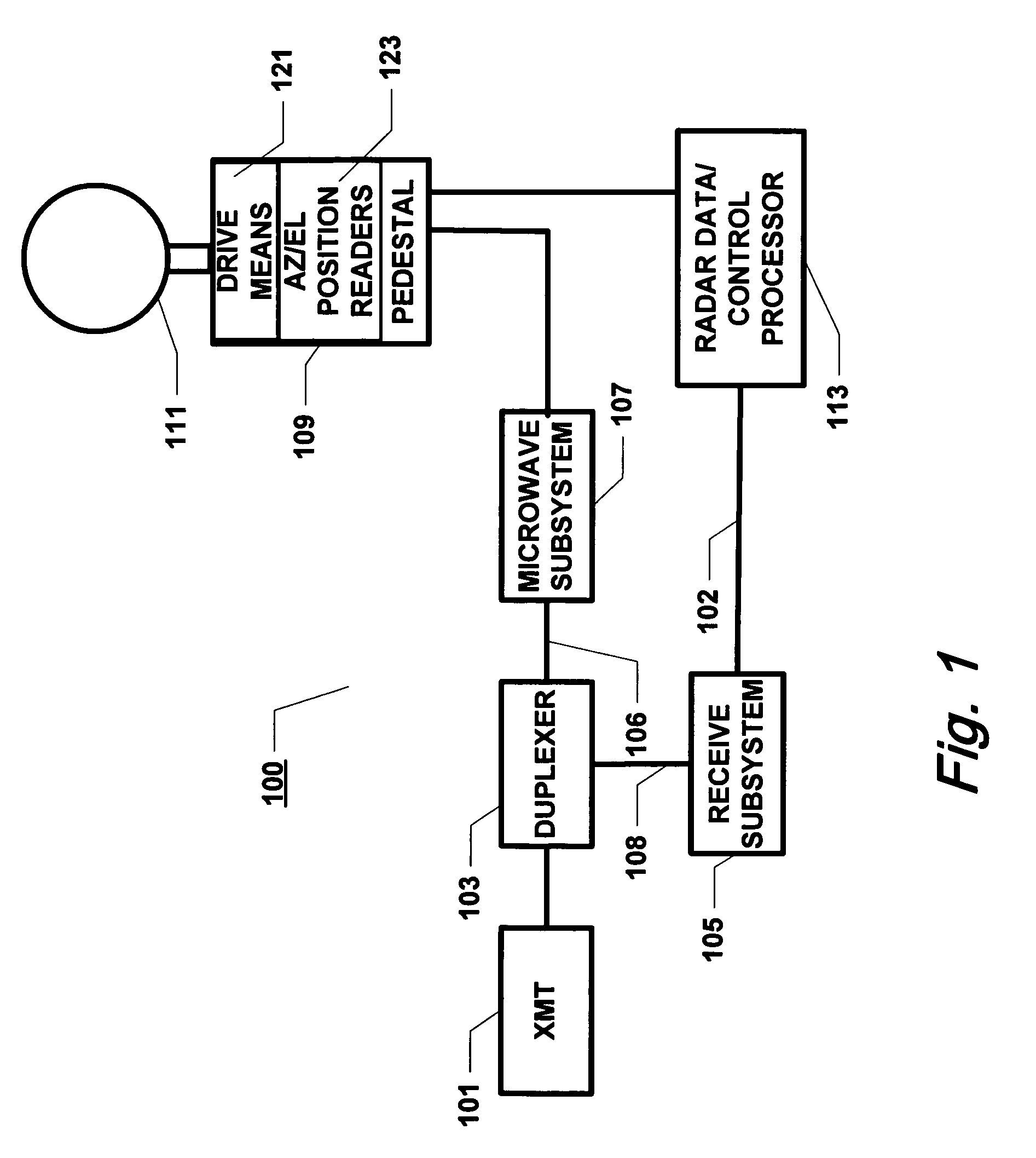
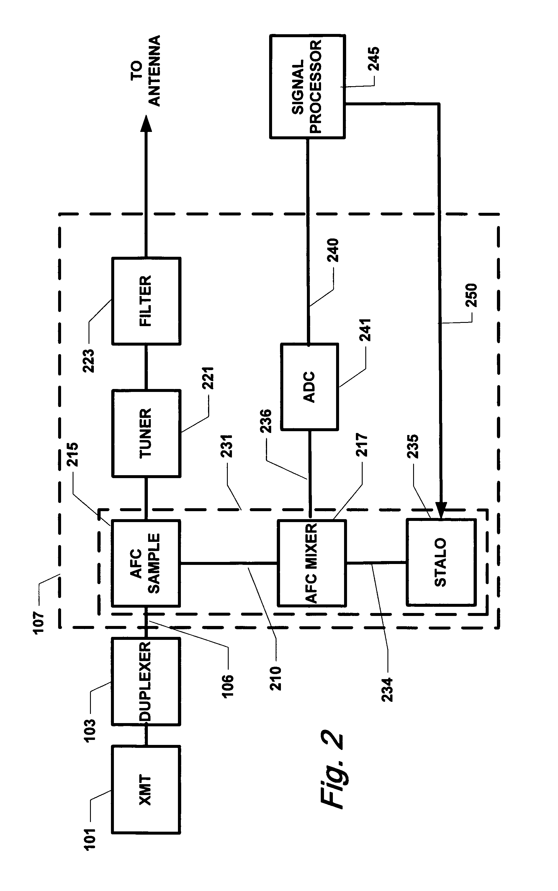
[0022]The various embodiments of the present invention and their advantages are best understood by referring to FIGS. 1 through 5 of the drawings. The elements of the drawings are not necessarily to scale, emphasis instead being placed upon clearly illustrating the principles of the invention. Throughout the drawings, like numerals are used for like and corresponding parts of the various drawings.

[0023]This invention may be provided in other specific forms and embodiments without departing from the essential characteristics as described herein. The embodiments described above are to be considered in all aspects as illustrative only and not restrictive in any manner. The appended claims rather than the foregoing description indicate the scope of the invention.

[0024]With reference to FIG. 1, an exemplary dual mode weather and air surveillance radar system 100 comprises a transmitter 101 having an output coupled to a duplexer 103. Duplexer 103 is further coupled to a transmit output 10...


PUM


Abstract

A radar system having first and second modes of operation comprising a dual antenna assembly comprising first and second antennas having respective first and second antenna waveguides coupled to a waveguide switch operable to divert RF energy to or from either said antenna waveguide, said waveguide switch coupled to a common waveguide, said dual antenna assembly mounted to an antenna support assembly, said first and second antennas being designed for use in said first and second modes respectively and operable for coupling said RF energy to a transmit medium, and for coupling reflected RF energy from transmit medium to said first or second antenna waveguide; and a control processor configured with control logic operable to control the functions of said radar system wherein said first and second antennas are mounted generally perpendicularly in the vertical plane with respect to each other and wherein said radar system operates in only one of said modes of operation at any time.

Description

BACKGROUND[0001]1. Field[0002]The present invention relates generally to radar systems, and, in particular, to radar systems having dual modes, and still more particularly, to radar systems having a weather radar mode and an air surveillance mode.[0003]2. Description of the Related Art[0004]Since the invention of detection and ranging using radio frequencies, different radar systems have been developed to meet the requirements of detecting different phenomena or objects. All radars work on the same basic principles of transmission of RF energy into the transmission medium (for example, the atmosphere), reception of reflected energy, (also known as backscatter or return energy), and analysis of the received energy to determine the presence and possibly characteristics of the detected object(s). Each type of radar system is optimized for the targets sought to be detected by the radar.[0005]For example, weather radar systems are tailored to detect airborne precipitation, known in the a...

Claims


Application Information

Patent Timeline
IPC IPC(8): G01S13/95
CPCG01S7/024G01S7/03G01S13/87G01S13/951H01Q3/08H01Q19/132H01Q21/28Y02A90/10
Inventor WALKER, WILLIAM H.
Owner BARON SERVICES
Learn More