Pole width control on plated bevel main pole design of a perpendicular magnetic recording head

a technology of perpendicular magnetic recording head and main pole, which is applied in the direction of magnetic recording head, data recording, instruments, etc., can solve the problems of large variation in the thickness of the resulting main pole layer, adverse effect of cmp process variation on device performance, and undesirable writing

Active Publication Date: 2010-03-02
HEADWAY TECH INC
View PDF16 Cites 24 Cited by
  • Summary
  • Abstract
  • Description
  • Claims
  • Application Information

AI Technical Summary

Problems solved by technology

However, a subsequent chemical mechanical polish (CMP) process that planarizes the main pole layer 3 is difficult to control and a large variation in the resulting main pole layer thickness may occur.
The thickness difference (t1−t2) caused by CMP process variation will have an adverse impact on device performance since track width and magnetic flux density delivered by the main pole will vary from one write head to the next.
In some cases where the skew angle α is large or where the undercut angle β is significant, undesirable writing can occur on a track adjacent to the intended recording track.

Method used


Image

  • Pole width control on plated bevel main pole design of a perpendicular magnetic recording head
  • Pole width control on plated bevel main pole design of a perpendicular magnetic recording head
  • Pole width control on plated bevel main pole design of a perpendicular magnetic recording head

Examples


Embodiment Construction

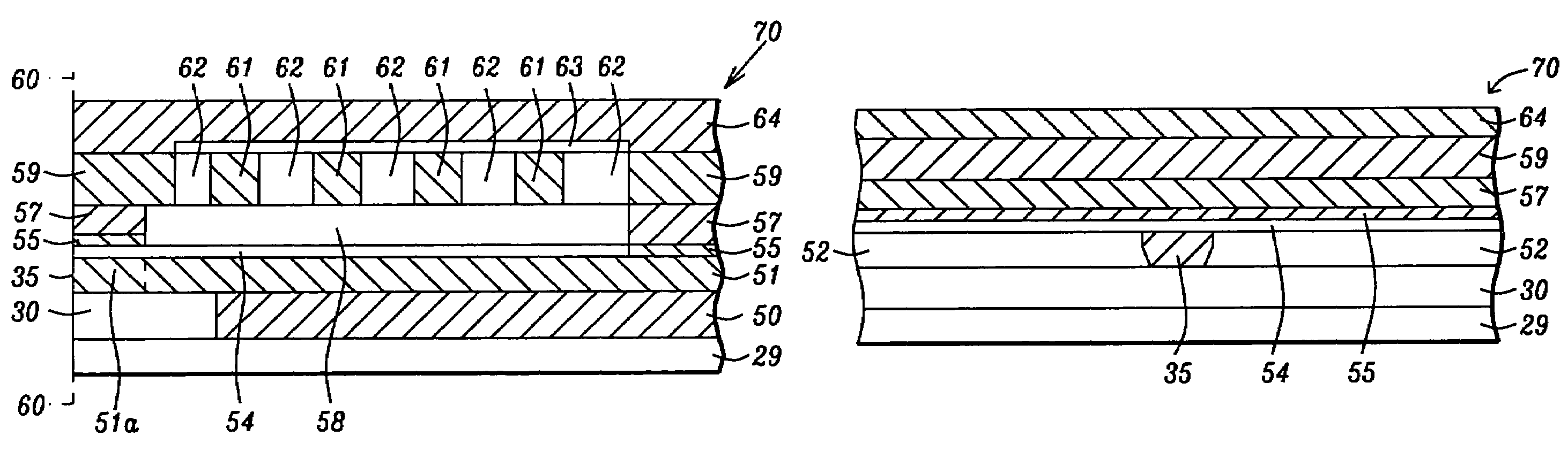
[0030]The present invention is a write pole in a PMR write head for use with magnetic storage media in a disk drive. A key feature is a main pole layer in which a pole tip region is comprised of an upper rectangular portion and a lower portion with an inverted trapezoidal shape. The upper portion has a leading edge along an ABS while the lower portion has a trailing edge in a recording operation. The present invention is also a method for forming a consistent pole width in a main pole layer that is not influenced by CMP process variations. The drawings are provided by way of example and are not intended to limit the scope of the invention. Moreover, the elements in the figures are not necessarily drawn to scale and may have different relative sizes in an actual device.

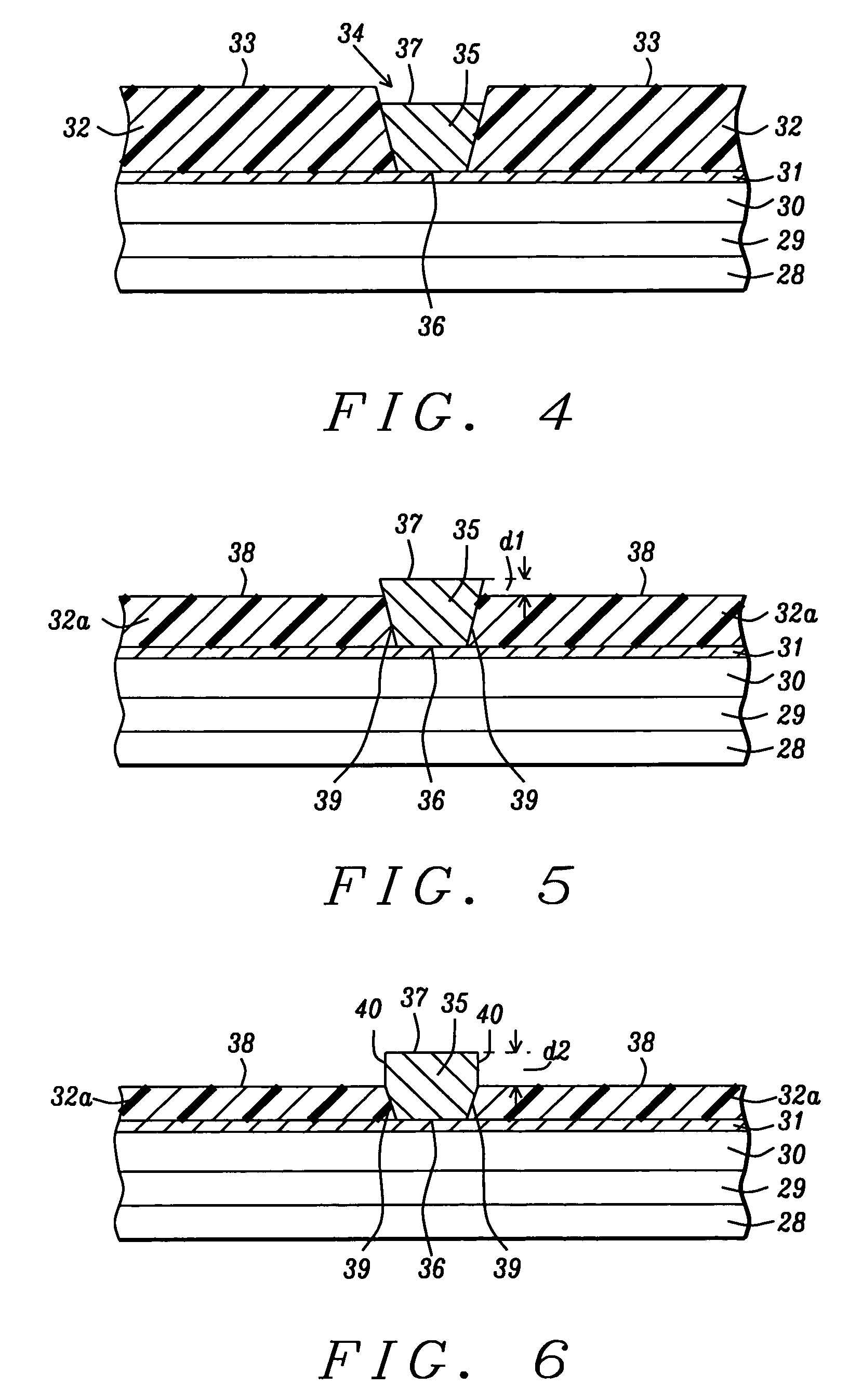
[0031]First a method of forming the pole tip according to the present invention will be described. Referring to FIG. 4, a cross-sectional view is shown from a first plane that will subsequently become an ABS as appreci...


PUM

PropertyMeasurementUnit
widthaaaaaaaaaa
widthaaaaaaaaaa
thicknessaaaaaaaaaa

Abstract

A main pole layer is deposited within an opening in a patterned photoresist layer on a substrate. The photoresist is thinned to expose an upper portion of a pole tip region that is then trimmed to a rectangular shape while a lower portion retains an inverted trapezoidal shape. Thereafter, a second trimming process forms a pole tip with a first width in the upper rectangular portion and a second thickness and second width which is less than the first width in the lower portion. A CMP step subsequently thins the upper portion to a first thickness of 0.04 to 0.08 microns while the second thickness remains at 0.16 to 0.32 microns. The bottom surface of the lower portion along the ABS becomes the trailing edge in a recording operation. The pole tip has a consistent first width (track width) that is not influenced by CMP process variations.

Description

FIELD OF THE INVENTION[0001]The invention relates to a write pole in a perpendicular magnetic recording head (PMR) and a method for making the same. In particular, a write pole having a rectangular upper portion and a trapezoidal lower portion is used to minimize variations in pole width caused by pole thickness variations.BACKGROUND OF THE INVENTION[0002]Perpendicular recording has been developed in part to achieve higher recording density than is realized with longitudinal recording devices. A PMR write head typically has a main pole with a small surface area at an air bearing surface (ABS) and a flux return pole (opposing pole) which is magnetically coupled to the main pole and has a large surface area at the ABS. Critical dimensions of the main pole include a neck height and a pole width in a pole tip adjacent to the ABS. Magnetic flux generated in the main pole layer passes through the pole tip into a magnetic media and then back to the write head by entering the flux return po...

Claims


Application Information

Patent Timeline
Patent Type & Authority Patents(United States)
IPC IPC(8): G11B5/127
CPCG11B5/1278G11B5/3163Y10T29/49044Y10T29/49048Y10T29/49032Y10T29/49043Y10T29/49046Y10T29/49052
Inventor LI, DONGHONGSASAKI, YOSHITAKA
Owner HEADWAY TECH INC
Why Eureka
Try Eureka