Remote radio data communication system with data rate switching

a radio data communication and data rate technology, applied in the direction of transmission monitoring, emergency power supply arrangement, electromagnetic radiation sensing, etc., can solve the problems of reducing the effective communication range, excessive digital noise generation in and around the rf terminal, etc., and achieve the effect of efficient operation and efficient conservation of transmission energy

Inactive Publication Date: 2010-03-02
AVAGO TECH INT SALES PTE LTD
View PDF117 Cites 36 Cited by
  • Summary
  • Abstract
  • Description
  • Claims
  • Application Information

AI Technical Summary

Benefits of technology

[0019]As stated above, high system clock rates are required in rf terminals to provide for the decoding of barcode scans at a rate that is acceptable to a user of the system. However, the high clock rates used for decoding also may cause the generation of an excessive amount of digital noise in and around the rf terminals. This noise can get into the rf terminal and interfere with communication, resulting in a reduction in the effective communication range. This problem is solved by using a dual clock rate. The terminal is operated normally at a slow system clock rate to minimize the generation of digital noise, and is switched to a fast clock rate during barcode scanning to allow the data obtained from the barcode scan to be processed at a higher rate. This lets the rf data link co-exist with the need for and the hardware support for barcode scan decoding.
[0050]Another object of the invention is to provide a radio data communication system utilizing a dormant polling protocol to efficiently conserve transmission energy.

Problems solved by technology

However, the high clock rates used for decoding also may cause the generation of an excessive amount of digital noise in and around the rf terminals.
This noise can get into the rf terminal and interfere with communication, resulting in a reduction in the effective communication range.

Method used


Image

  • Remote radio data communication system with data rate switching
  • Remote radio data communication system with data rate switching
  • Remote radio data communication system with data rate switching

Examples


Embodiment Construction

List of Appendices

[0107]Appendix A. Brochure entitled “MBA3000 Multiple Base Adapter”.

[0108]Appendix B. Brochure entitled “RB2212 Base Radio Transceiver”.

[0109]Appendix C. Brochure entitled “RB3000 Base Radio Transceiver”.

[0110]Appendix D1. Brochure entitled “RT2210XL Radio Data Terminal”.

[0111]Appendix D2. Brochure entitled “RT3210 Radio Data Terminal”.

[0112]Appendix D3. Brochure entitled “RT3310 & RT3410 Radio Data Terminals”.

[0113]Appendix D4. Brochure entitled “RT1000 Radio Data Terminal”.

[0114]Appendix D5. Brochure entitled “RT5910 Mobile Mount Radio Terminal”.

[0115]Appendix E. Exemplary Program Listing Showing Control Instructions of a Network Controller.

[0116]Appendix F. Exemplary Program Listing Showing Control Instructions for a Protocol of a Mobile Transceiver Unit.

[0117]Appendix G. Brochure entitled “RM3216 Communication Multiplexer”.

[0118]Appendix H. Exemplary Command Structure for a Mobile Transceiver Unit.

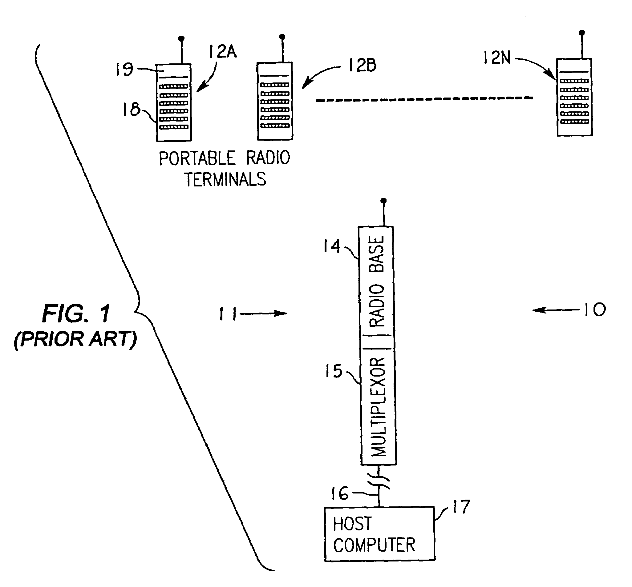
[0119]FIG. 1 shows an existing radio frequency data transmission...


PUM


Abstract

Systems and methods that provide wireless communications are provided. One or more of the systems and methods may include, for example, selecting a lower data rate or a higher data rate based upon at least an evaluation of the operating conditions of a radio network. The evaluation may include, for example, computing a weighted signal strength measurement in which the weighting gives emphasis to the lower signal strength measurements of fading radio frequency signals.

Description

CROSS-REFERENCE TO RELATED APPLICATIONS[0001]The present application is a continuation of U.S. patent application Ser. No. 10 / 057,816 filed Jan. 24, 2002, which is a consolidation of application Ser. Nos. 09 / 934,457 Aug. 21, 2001 and 09 / 799,340 Mar. 5, 2001. Said application Ser. No. 10 / 057,816 is a continuation-in-part of said application Ser. No. 09 / 934,457 filed Aug. 21, 2001 now abandoned and said application Ser. No. 10 / 057,816 Jan. 24, 2002 is a continuation-in-part of said application Ser. No. 09 / 799,340 filed Mar. 5, 2001 now abandoned. Said application Ser. No. 09 / 934,457 Aug. 21, 2001 is a continuation of application Ser. No. 08 / 551,442 filed Nov. 1, 1995, which is a continuation of application Ser. No. 07 / 910,865 filed Jul. 6, 1992, now abandoned; said application Ser. No. 07 / 910,865 is a continuation-in-part of application Ser. No. 07 / 864,300 filed Apr. 6, 1992, now abandoned; and a continuation-in-part of Application Ser. No. 07 / 980,947 filed May 26, 1992, now abandoned...

Claims


Application Information

Patent Timeline
Patent Type & Authority Patents(United States)
IPC IPC(8): H04W72/00G06F1/16G06K7/10G06K17/00G06Q10/08G06Q20/34G07F7/02G07G1/00G08C17/02H01Q1/22H02J9/00H04B1/16H04B1/38H04B1/69H04B1/707H04B1/713H04B7/005H04B17/00H04L1/00H04L12/28H04L12/403H04L12/56H04L29/06H04M1/73
CPCG06F1/163G06K7/10722G06K7/10881G06K7/1093G06K7/1098G06K17/0022G06Q10/08G06Q20/343G07F7/02G07G1/0045G08C17/02H01Q1/22H02J9/005H04B1/69H04B1/707H04B1/713H04L1/0002H04L1/0003H04L1/0007H04L1/0014H04L1/0025H04L1/0032H04L29/06H04W52/343H04B17/309G06F1/1632H04B17/318G08C2201/20H04B1/3883H04B17/0085H04B2001/3894H04B2201/7071H04W52/029H04L69/18H04L69/24Y02D30/70H04L9/40
Inventor MAHANY, RONALD L.LUCKEN, LEGAL REPRESENTATIVE, PAMELA
Owner AVAGO TECH INT SALES PTE LTD
Why Eureka
Try Eureka