
Multi-purpose mobile power generating machine

a power generation machine and multi-purpose technology, applied in the field of mobile machines, can solve the problems of increasing the operational cost of the worksite, increasing the cost of transportation, and high transportation costs of each of the equipment to and from the worksi

Active Publication Date: 2010-03-09
CATERPILLAR INC
View PDF51 Cites 32 Cited by
  • Summary
  • Abstract
  • Description
  • Claims
  • Application Information

AI Technical Summary

Benefits of technology

The patent text describes three aspects of a mobile machine that can generate and use electrical power. The first aspect is a mobile machine that has a power source to move and use power off the machine. The second aspect is a mobile machine that has a power source and a work tool driven by the power source. The third aspect is a mobile machine that has an internal combustion engine and a generator to produce power. The mobile machine also has a traction device to move and a motor to drive the traction device. The mobile machine can manage its power output based on the operating mode input. The technical effects of this patent text are that it describes how to generate and use electrical power on a mobile machine, which can improve its efficiency and performance.

Problems solved by technology

Although the machines described above may be quite efficient in accomplishing their respective predetermined tasks, they may also be expensive and costly to transport.
The number of different pieces of equipment operating or sitting idle at the same worksite increases the operational cost of the worksite.
In addition, transportation of each of the pieces of equipment to and from the worksite may be expensive, particularly when the worksite is remote from the current location of the machines.
Although the multipurpose nature of the electric car described in the '289 patent may offset the initial cost of the car and some transportation costs associated with the remote location, its use and benefit may be limited.
That is, without a work tool, the car's only purpose at the worksite may be power generation and, because of its size and configuration, the amount of power and the output variability of the power provided by the car may be insufficient to support worksite operations.

Method used


Image

  • Multi-purpose mobile power generating machine
  • Multi-purpose mobile power generating machine
  • Multi-purpose mobile power generating machine

Examples


Embodiment Construction

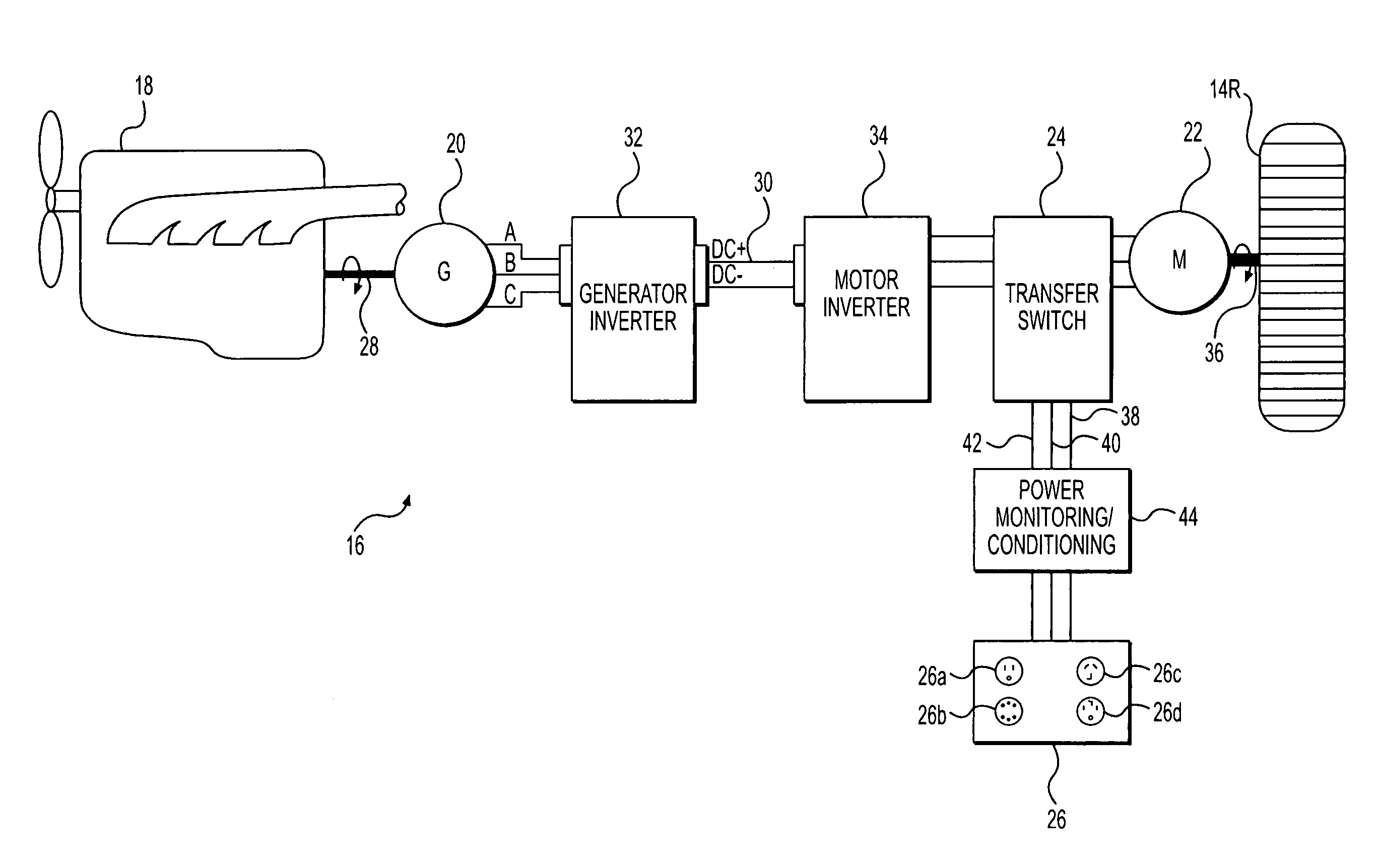
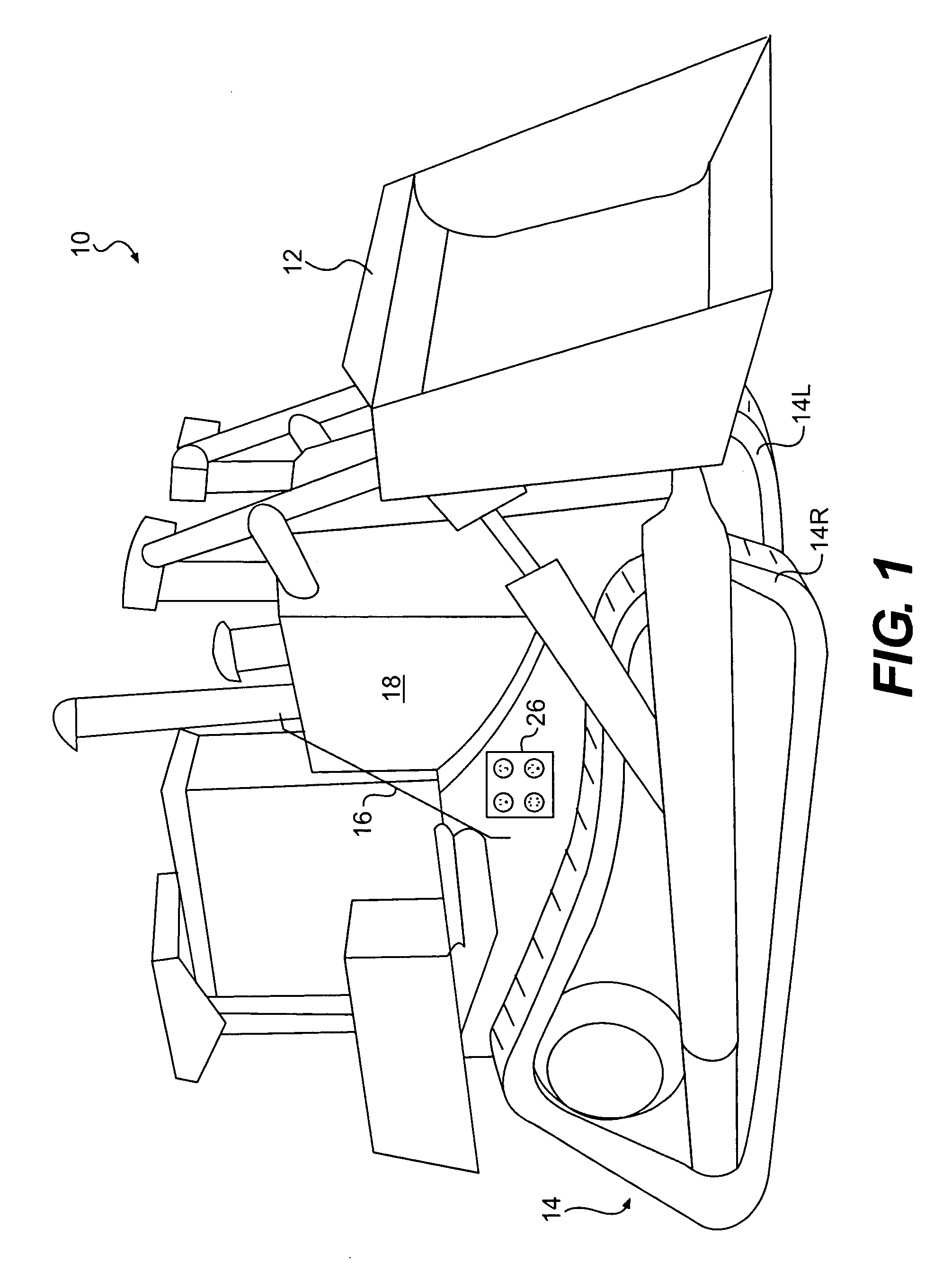
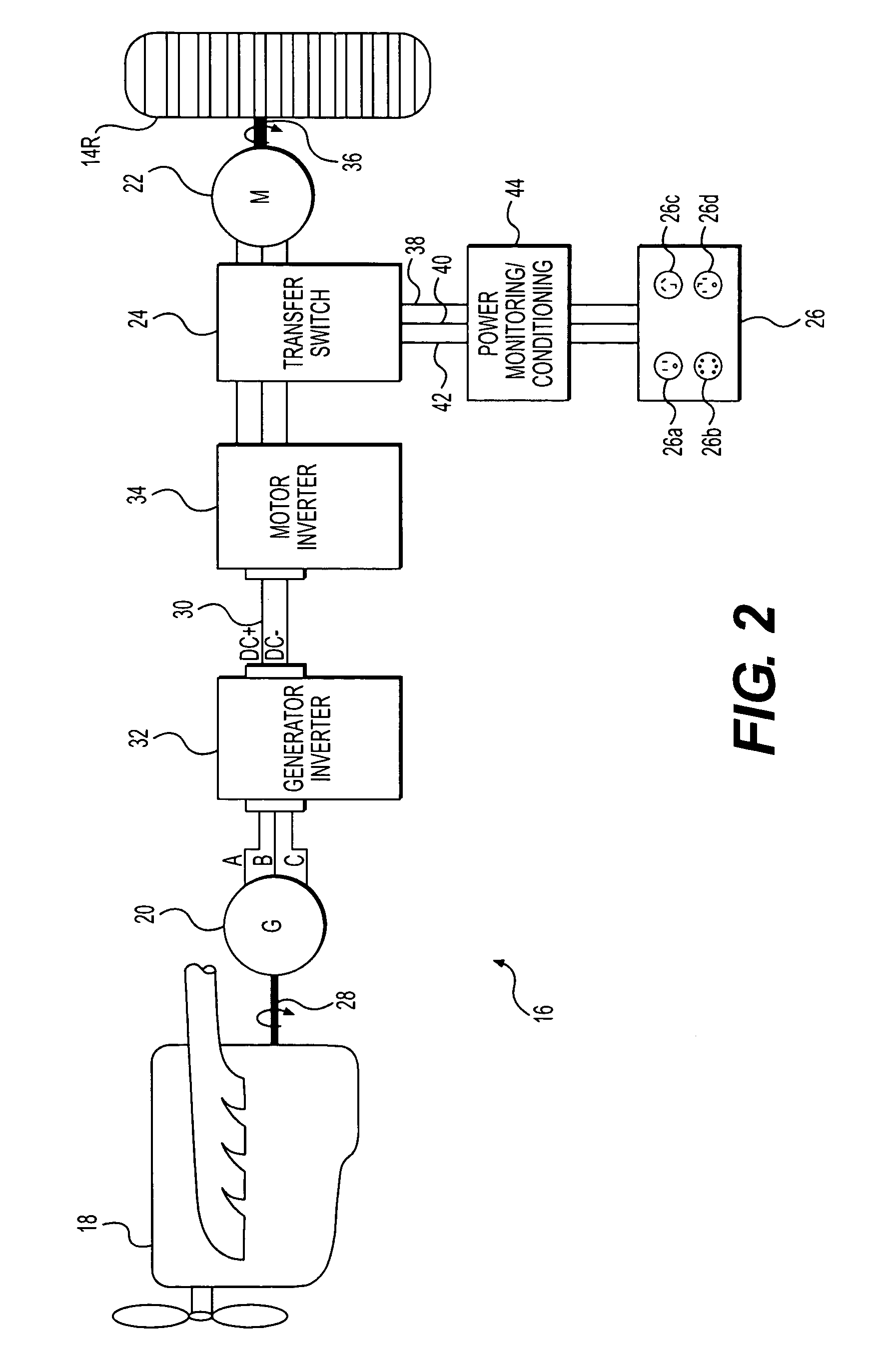
[0012]FIG. 1 illustrates an exemplary machine 10. Machine 10 may be a mobile machine that performs some type of operation associated with an industry such as mining, construction, farming, transportation, or any other industry known in the art. For example, machine 10 may be an earth moving machine such as the track-type tractor depicted in FIG. 1. Machine 10 may alternatively embody a non-earthmoving machine such as an on-highway truck, a passenger vehicle, or any other suitable operation-performing machine. Machine 10 may include a work tool 12, a traction device 14, and a power system 16 configured to transmit a power output to work tool 12 and traction device 14 in response to an operator input.

[0013]Numerous different work tools 12 may be attachable to a single machine 10 and controllable by an operator of machine 10. Work tool 12 may include any device used to perform a particular task associated with a surface or object offboard machine 10. For example, work tool 12 may embod...


PUM


Abstract

A dual purpose mobile machine is disclosed. The mobile machine may have a power source configured to propel the mobile machine and generate electrical power for use offboard the mobile machine. The machine may also have a work tool driven by the power source.

Description

TECHNICAL FIELD[0001]The present application is directed to a mobile machine and, more particularly, to a mobile machine having multiple purposes, one of which includes power generation.BACKGROUND[0002]Machines such as, for example, track-type tractors, wheel loaders, haul trucks, and other heavy construction, agriculture, and mining equipment are used to perform many tasks such as, for example, digging, dozing, loading, tilling, hauling, power generation, and other similar duties. To effectively perform these tasks, each different machine requires a power source that provides significant power to a drivetrain arrangement and / or a tool arrangement. The power source may be a combustion engine such as, for example, a turbine engine, a diesel engine, a gasoline engine, or a gaseous fuel-powered engine operated to generate a torque output at a range of speeds. This torque output may be transmitted from the power source through a transmission to a ground engaging traction device such as ...

Claims


Application Information

Patent Timeline
Patent Type & Authority Patents(United States)
IPC IPC(8): B60K1/00B60K6/20B60K6/42B60K6/46B60W20/00
CPCB60L1/003B60L1/006B60L1/20B60L2200/40B60L2220/18B60L58/10B60L58/30Y02T10/70Y02T90/40
Inventor BETZ, MICHAEL D.CARUTHERS, MICHAEL A.GARNETT, STEPHEN C.SHULTS, RICHARD F.UNGER, BRUCE E.
Owner CATERPILLAR INC
Learn More